
Owners Manual
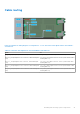
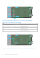
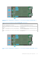
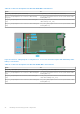
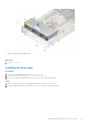
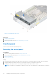
Table Of Contents
- Dell EMC PowerEdge MX750c Installation and Service Manual
- Contents
- About this document
- Dell EMC PowerEdge MX750c system overview
- Initial system setup and configuration
- Minimum to POST and system management configuration validation
- Installing and removing system components
- Safety instructions
- Before working inside your system
- After working inside your system
- Recommended tools
- PowerEdge MX750c sled
- Sled cover
- Air shroud
- Processor and memory module blank
- Drives
- Drive backplane
- Cable routing
- Drive cage
- Control panel
- System memory
- Processor and heat sink module
- PERC card
- Optional IDSDM module
- M.2 BOSS card
- Mezzanine cards
- Optional internal USB memory key
- System battery
- System board
- Trusted Platform Module
- Upgrade Kits
- Jumpers and connectors
- System diagnostics and indicator codes
- Getting help
- Documentation resources

Figure 38. SAS/PCIe cabling diagram of configuration 9 - 4 x 2.5-inch Universal backplane with HBA350i MX + on
board PCIe
Table 14. Connector descriptions for SAS with HBA350i MX+ on board PCIe
From To
BP_PWR_1 (backplane power connector) SIG_PWR_0 (system board power connector)
BP_DST_PA1 (backplane PCIe 1 connector, cable marking
BP_PA1)
SL1_CPU1_PA1 (signal connector on the system board, cable
marking MB SL1)
BP_DST_SA1 (backplane SAS connector, cable marking BP
SA1)
CTRL_SRC_SA1 (SAS connector of HBA350i MX controller
card, cable marking CTRL_SA1)
BP_DST_PB1 (backplane PCIe 2 connector, cable marking BP
PB1)
SL2_CPU1_PB1 (signal connector on the system board, cable
marking MB SL2)
Figure 39. SAS/PCIe cabling diagram of configuration 9 - 4 x 2.5-inch Universal backplane with H755 MX + on board
PCIe
Installing and removing system components
45