
Owners Manual
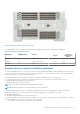
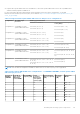
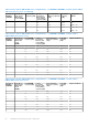

Table Of Contents
- Dell EMC PowerEdge MX750c Installation and Service Manual
- Contents
- About this document
- Dell EMC PowerEdge MX750c system overview
- Initial system setup and configuration
- Minimum to POST and system management configuration validation
- Installing and removing system components
- Safety instructions
- Before working inside your system
- After working inside your system
- Recommended tools
- PowerEdge MX750c sled
- Sled cover
- Air shroud
- Processor and memory module blank
- Drives
- Drive backplane
- Cable routing
- Drive cage
- Control panel
- System memory
- Processor and heat sink module
- PERC card
- Optional IDSDM module
- M.2 BOSS card
- Mezzanine cards
- Optional internal USB memory key
- System battery
- System board
- Trusted Platform Module
- Upgrade Kits
- Jumpers and connectors
- System diagnostics and indicator codes
- Getting help
- Documentation resources

● Populate Intel Optane PMem 200 Series in DIMM slot 1, unless Intel Optane PMem 200 Series is the only DIMM in that
channel, and then populate in DIMM slot 0.
For more information about the supported Intel Persistent Memory 200 series (BPS) configurations, see the Dell
EMC Intel Persistent Memory 200 series (BPS) User's Guide at https://www.dell.com/support/home/products/server_int/
server_int_poweredge.
Table 22. Supported Intel Optane PMem 200 Series for dual processor configurations
Configuration Description per
processor
Memory population rules
RDIMMs or LRDIMMs Intel Persistent Memory 200
series (BPS)
Configuration 1 4 x RDIMMs, 4 x Intel
Optane PMem 200 Series
Processor1 {A1, 2, 3, 4}
Processor2 {B1, 2, 3, 4}
Processor1 {A5, 6, 7 ,8}
Processor2 {B5, 6, 7, 8}
Configuration 2 6 x RDIMMs, 1 x Intel
Optane PMem 200 Series
Processor1 {A1, 2, 3, 4, 5, 6}
Processor2 {B1, 2, 3, 4, 5, 6}
Processor1 {A7}
Processor2 {B7}
Configuration 3 8 x RDIMMs, 1 x Intel
Optane PMem 200 Series
Processor1 {A1, 2, 3, 4, 5, 6, 7, 8}
Processor2 {B1, 2, 3, 4, 5, 6, 7, 8}
Processor1 {A9}
Processor2 {B9}
Configuration 4 8 x RDIMMs, 4 x Intel
Optane PMem 200 Series
Processor1 {A1, 2, 3, 4, 5, 6, 7, 8}
Processor2 {B1, 2, 3, 4, 5, 6, 7, 8}
Processor1 {A9, 10, 11, 12}
Processor2 {B9, 10, 11, 12}
Configuration 5 8 x RDIMMs, 8 x Intel
Optane PMem 200 Series
Processor1 {A1, 2, 3, 4, 5, 6, 7, 8}
Processor2 {B1, 2, 3, 4, 5, 6, 7, 8}
Processor1 {A9, 10, 11, 12, 13, 14, 15,
16}
Processor2 {B9, 10, 11, 12, 13, 14, 15,
16}
Configuration 6 12 x RDIMMs, 2 x Intel
Optane PMem 200 Series
Processor1 {A1, 2, 3, 4, 5, 6, 7, 8, 9, 10, 11,
12, 15, 16}
Processor2 {B1, 2, 3, 4, 5, 6, 7, 8, 9, 10, 11,
12, 15, 16}
Processor1 {A5, 6}
Processor2 {B5, 6}
NOTE: There are limited configurations available for dual socket servers with only one processor populated.
Table 23. Intel Optane PMem 200 Series Configuration 1 - 4 x RDIMMs/ LRDIMMs, 4 x Intel Optane PMem
200 Series per processor
Total No of
RDIMMs/
LRDIMMs
Total No of
Intel Optane
PMem 200
Series DIMMs
1 R/LRDIMM
capacity (GB)
1 Intel
Persistent
Memory 200
series (BPS)
capacity (GB)
Total Standard
Memory Capacity
(GB)
Total PM
Capacity
(GB)
Supported
Modes
4 4 16 128 64 512 MM or AD
4 4 32 128 128 512 MM or AD
4 4 64 128 256 512 AD
4 4 128 128 512 512 AD
4 4 16 256 64 1024 MM or AD
4 4 32 256 128 1024 MM or AD
4 4 64 256 256 1024 MM or AD
4 4 128 256 512 1024 AD
Installing and removing system components 55