Dell EMC PMem 100 Series User's Guide April 2021 Rev.
Notes, cautions, and warnings NOTE: A NOTE indicates important information that helps you make better use of your product. CAUTION: A CAUTION indicates either potential damage to hardware or loss of data and tells you how to avoid the problem. WARNING: A WARNING indicates a potential for property damage, personal injury, or death. © 2017 - 2021 Dell Inc. or its subsidiaries. All rights reserved. Dell, EMC, and other trademarks are trademarks of Dell Inc. or its subsidiaries.
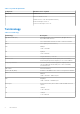
Contents Chapter 1: Introduction................................................................................................................. 5 System requirements..........................................................................................................................................................5 Terminology...........................................................................................................................................................................
Chapter 9: Windows.................................................................................................................... 34 PMem in App-direct mode.............................................................................................................................................. 34 PMem Disk management...........................................................................................................................................
1 Introduction Dell EMC now offers Intel Optane persistent memory (PMem), a nonvolatile memory that has the same form factor as a standard DDR4 DIMM. PMem in this document stands for AEP in 14G systems unless otherwise stated. PMems come in three capacities: 128 GB, 256 GB, and 512 GB. PMems are installed in the memory slots of the server and are compatible with RDIMMs and LRDIMMs.
Table 1. System Requirements Component Minimum version required PMem FW Build # 5375 OS Microsoft Windows 2019 VMware ESXi 6.7 with EP10 (Build #13981272) Red Hat Enterprise Linux 7.6 SUSE Linux Enterprise Server 15 Terminology Table 2. Terminology Terminology Description App-direct mode (AD) Persistent memory is accessed directly by applications as byte-addressable memory.
2 Change list Table 3.
3 Hardware Topics: • • • Server hardware configuration DIMM installation and removal PMem hardware configuration Server hardware configuration PMem is supported in R640, R740/R740XD, R840, R940, R940xa, MX740c, and MX840c PowerEdge servers with secondgeneration Intel Xeon Scalable Processors of Gold and Platinum grade. See PMem configurations for a list of fully supported and validated PMem configurations in two-socket servers. Four-socket configurations are a direct scale up of two-socket configurations.
Figure 1. Memory Layout for R740/R740XD Table 4. PMem configurations Number PMem of CPUs Populat in the ion Server DRAM Populat ion DRAM Capacit y (GB) PMem Capacit y (GB) OS Total Memory Memory in (GB) Memory Mode (GB) Total Memory per CPU (GB) Ratio DRAM to Optane Memory Require s an M or L CPU Support ed in App Direct Mode Support ed in Memory Mode 1 128 GB x 16 GB x 2 4 64 256 256 320 320 1:4 No Yes Yes 1 128 GB x 16 GB x 1 6 96 128 NA 224 224 1:1.
Table 4. PMem configurations Number PMem of CPUs Populat in the ion Server DRAM Populat ion DRAM Capacit y (GB) PMem Capacit y (GB) OS Total Memory Memory in (GB) Memory Mode (GB) Total Memory per CPU (GB) Ratio DRAM to Optane Memory Require s an M or L CPU Support ed in App Direct Mode Support ed in Memory Mode 2 128 GB x 16 GB x 4 8 128 512 512 640 320 1:4 No Yes Yes 2 128 GB x 16 GB x 4 12 192 512 NA 704 352 1:2.
Table 4. PMem configurations Number PMem of CPUs Populat in the ion Server DRAM Populat ion DRAM Capacit y (GB) PMem Capacit y (GB) OS Total Memory Memory in (GB) Memory Mode (GB) Total Memory per CPU (GB) Ratio DRAM to Optane Memory Require s an M or L CPU Support ed in App Direct Mode Support ed in Memory Mode 2 256 GB x8 64 GB x 12 768 2,048 NA 2,816 1,408 1:2.
Table 5.
Table 6.
Table 6. Dual socket PMem population CPU 0 and CPU 1 PMem DRA M Channel 2 Channel 1 Channel 0 Channel 0 Channel 1 Channel 2 A3, B3 A2, B2 A1, B1 A7, B7 A10, B10 A4, B4 A11, B11 A5, B5 A12, B12 A6, B6 A9, B9 A8, B8 256 GB x 12 64 GB x 12 DRAM PMem DRA M PMem DRAM PMem PMem DRAM PMem DRAM PMem DRAM 256 GB x 12 128 GB x 12 DRAM PMem DRA M PMem DRAM PMem PMem DRAM PMem DRAM PMem DRAM Table 7.
Table 7.
CPU type and maximum memory limits Table 8. CPU type and maximum memory limits CPU type Maximum memory supported (Includes voltaile and persistent memory capacity) All CPU SKUs 1 TB per CPU socket M SKUs 2 TB per CPU socket L SKUs 4.5 TB per CPU socket PMem mixing and population rules This section has general rules for DIMM mixing and population. Each system must contain only one capacity of PMem. If you mix PMem capacities, an F1/F2 warning message is displayed.
4 BIOS Topics: • • • BIOS configuration setting for Intel PMem App-direct mode configuration Memory mode configuration BIOS configuration setting for Intel PMem DIMM discovery All installed PMems that the BIOS has discovered during system inventory is displayed in the BIOS Intel Persistent Memory tab: Memory Settings > Persistent Memory > Intel Persistent Memory > Persistent Memory DIMM Configuration. Figure 2. Persistent Memory screen NOTE: PMems are shown as DIMMs.
Figure 3. Memory info NOTE: Data is always assumed to be in units of MiB/GiB/TiB even if labeled MB/GB/TB. User capacity overhead is up to 2% of capacity (GiB). Another overhead may be required for Regions, Namespace, and Filesystems. App-direct mode configuration Create goal Goal is created in BIOS. To create a goal in BIOS, go to: Memory Settings > Persistent Memory > Intel Persistent Memory > Region Configuration > Create Goal Config.
Figure 4. Goal configuration The BIOS options determine how the goal is created and the PMems are configured: Persistent [%]: ● No Change - Does not apply any changes to the current goal. ● 100 - Creates a goal of 100% Persistent memory across the selected PMems. ● 0 - Creates a goal of 0% Persistent memory across the selected PMems. This operation configures all the PMem as Memory mode. Persistent memory type: ● App-direct Interleaved - Persistent mode interleave across the PMems in a scoket.
Figure 5. Region configuration The number of regions that are displayed depends on the number of processors in the system and not on the PMems interleaved. If the PMems are configured as interleaved, one Persistent Memory Region is listed per socket in the system that has PMems installed. If the PMems are configured as non-interleaved, one Persistent Memory Region is listed per PMem installed in the system. Region information can be accessed by clicking each Persistent Memory Region link in the BIOS.
Figure 6. Region info Memory mode configuration Create goal Goal is created in the BIOS. To create a goal in BIOS, go to: Memory Settings > Persistent Memory > Intel Persistent Memory > Region Configuration > Create Goal Config. The BIOS options determine how the goal is created and the PMems are configured: Operation Target: ● Platform - Applies the goal to all the DIMMs in the system (recommended). Persistent [%]: ● No Change - Does not apply any changes to the current goal.
5 PMem event reporting When system detects PMem-related event either during runtime or POST, system will log the events in Server System Event Log(SEL) and Life-Cycle Log(LCL). If an event is detected during boot time, system halts during the POST and user needs to press F1 to continue the boot process. NOTE: NVDIMM is frequently used in these messages. The term NVDIMM is generic to several different families of persistent memory including PMem and not meant to indicate NVDIMM-N modules.
Recommended Action: N/A ● UEFI0347 : Unable to initialize the memory because one or more errors have occurred during the NVDIMM initialization in the slot . Recommended Action : Manually remove and reinstall the NVDIMM. If the issue persists, contact your service provider. For more information about removing and reinstalling an NVDIMM, see the product Installation and Service Manual available on the support site.
Recommended Action : Retry the operation. If the issue persists, contact your service provider. ● UEFI0359 : The Overwrite DIMM operation on the Intel Persistent Memory DIMM with serial number in slot is successfully completed. Recommended Action : N/A NOTE: This is part of the PMem Sanitize function. ● UEFI0360 : Unable to complete the Overwrite DIMM operation on the Intel Persistent Memory DIMM with serial number in slot .
Recommended Action : Do one of the following: 1) Power off the server. 2) Disconnect the input power, wait for 30 seconds, and then reconnect to the power source. 3) Power on the server. 4) If the issue persists, contact your service provider. ● PWR2281 : Unable to perform the memory arming operation because the PSU configuration of the server is insufficient to guarantee data flush time in the event of power loss. Recommended Action : Do the following and retry the operation: ○ Turn off the server.
6 iDRAC Intel PMem management Topics: • iDRAC GUI iDRAC GUI PMem firmware version PMem FW version is displayed under System > Inventory > Firmware inventory tab. Figure 7. PMem firmware version PMem hardware status Select the Memory link on the Dashboard to get more information about memory health. PMem hardware status is displayed under System > Inventory > Hardware inventory tab.
Figure 8. PMem hardware status PMem goal configuration using iDRAC GUI 1. Log on to iDRAC GUI interface. 2. Navigate to Configuration > BIOS settings > Memory settings > Persistent Memory Settings tab. Figure 9. PMem goal configuration using iDRAC GUI 3. Navigate to Intel Persistent Memory > Region Configuration > Create Goal Config.
Figure 10. PMem goal configuration 4. Change Persistent percentage as 100% to configure Intel PMem into 100% App-direct Mode and 0% to configure the DIMMs into 100% memory mode. NOTE: The Persistent memory type field is for configuring a new goal. It is not for reading the status of the current goal. Use instructions under PMem Hardware Status to confirm current configuration. 5. Click Apply and reset the system. 6.
7 PMem security Topics: • • • Memory mode App-direct Cryptographic erase and PMem sanitize Memory mode In Memory mode PMems operate as volatile system memory. User passphrase is not supported and this BIOS setting will be greyed out. App-direct Users have the option to enable Passphrase protection of PMem regions. The intent of the passphrase is to protect against unauthorized access to data stored on the PMem region.
Figure 12.
Both erase methods can be executed using BIOS setup options. User can choose to perform an erase on all or a subset of installed PMems. Crypto erase The Crypto Erase function erases the App-direct Region Key (PM-RK) forcing the system to reboot. Cryptographic erase option can be accessed by going to: System BIOS Settings > Memory Settings > Persistent Memory > Intel Persistent Memory > Persistent Memory DIMM Configuration Figure 13.
Sanitize can take up to 15 minutes with fully loaded 128 GB DIMM configuration, 30 minutes with 256 GB and 1 hour with 512 GB. NOTE: Sanitize is not supported when PMems are configured in Memory mode. When the Sanitize operation is running, a prompt appears in BIOS indicating an Overwrite. Overwrite is the name for the second firmware command that is conducted. The first command which happens quickly and will not be displayed on-screen is the Crypto Erase (firmware command name is "Secure Erase").
8 DIMM configuration changes The following PMem migration scenarios are supported: ● Replacement of System Board due to failure All DIMMs must be re-populated in the exact same slots. PMems and data content will be available for customer application access after the board has been restored to the same configuration as the original board. System Restore will automatically restore the BIOS configuration on the replacement board, including the PMem Passphrase, if it is set.
9 Windows Dell EMC supports Intel Optane PMem with Microsoft Windows 2019 in Memory mode and App-direct mode. NOTE: Keep Windows updated with the monthly cumulative updates.
Figure 16. Memory Devices in Device Manager PMem Disk management Windows currently supports only one namespace per interleave set (this is independent of the number of physical devices in the interleave set). The option to interleave PMems can be selected during goal creation as described in App Direct and Memory mode configurations. PMem disks have to be created with the help of "New-Pmemdisk" command by providing relevant region IDs.
○ This cmdlet is intended as a “big hammer” recovery mechanism. It is not recommended for normal use. List PMem physical disks and check their health status The following image displays command usage to list all usage to list all PMem physical devices and get their health. Physical location gives the location of the DIMM on the motherboard. Figure 17.
Remove PMem disks Figure 19. Remove PMem disks Windows 2019 does not support redundant volume creation on PMem disks by using Windows VDS (Virtual disk service). In order to create redundant volumes, use the storage spaces method. For information about storage spaces method refer to: https://docs.microsoft.com/en-us/windows-server/storage/storagespaces/deploy-standalone-storage-spaces.
Figure 21. PMem Disk creation using Region id PMem in memory Mode When Intel Optane PMem is configured in memory mode, operating system sees it as system memory. Persistent memory size is shown as zero and volatile memory size accounts for the entire size of the PMem. Figure 22. PMem in memory Mode Windows troubleshooting and event monitoring If any of the PMem physical devices or logical devices are not functioning properly, it is suggested to check Windows event logs.
Figure 23. Windows troubleshooting and event monitoring Windows Errata The following errata affects Windows OSes and are expected to be fixed in a future OS patch. ● When a namespace is created in Windows Server 2019 (WS2019), the logged message appears as "The driver for persistent memory disk encounters internal error". The error is expected and it may occur during testing of Storage Class Memory (SCM) device. This means the namespace is created, and is considered as WAD for WS2019. Workaround: None.
10 Linux Topics: • • • Identify and configure persistent memory device Management utility Linux errata Identify and configure persistent memory device Listing PMem devices To list all physical devices in the system, run command ndctl list -DHi Create namespace The configuration of namespaces will decide how much memory capacity user wants to expose to the OS.
To write data into the device, run the following command: cd /mnt/pmemX echo “Hello World” >>test.txt Reset the system and the data should be persistent over power cycle. Delete namespaces Namespace can be deleted using NDCTL command: ndctl destroy-namespace is namespaceX.
Workaround: Add "x-systemd.device-timeout=0" to the mount options for the PMem partition in fstab. Example: /dev/pmem5 /mnt/somedir ext4 defaults, x-systemd.device-timeout=0,dax 0 2 3. Dell BIOS does not support boot from PMem. Some Linux operating system (Red Hat Enterprise Linux 7.6, Red Hat Enterprise Linux 8.0) distros are offering early support of this feature, but Dell BIOS does not support this feature. Workaround:None.
11 VMware ESXi Dell EMC supports Intel Optane PMem from vSphere 6.7 EP10 (Build #13981272) and above. The support is available for Intel PMem Memory mode and App-direct modes. The persistent memory inventory details are available as part of Host client. See Managing Persistent Memory in the vSphere Single Host Management - VMware Host Client which detail the persistent memory data that are presented to the user.
Figure 26. Namespaces created on ESXi out of the interleave sets exposed After creating the namespaces, ESXi automatically creates a PMem datastore and mounts it as a datastore for the users to consume it. Figure 27. PMem Datastore PMem in Memory mode When Intel PMem is configured in memory mode, ESXi sees it as system memory. NOTE: The inventory details in the vSphere HTML client will not be available if Intel PMem is set to Memory mode.
ESXi troubleshooting and maintenance NOTE: Go through /var/log/vmkernel.log to see if there are any errors or warnings reported related to persistent memory. The log entries related to persistent memory would be appended with "NVD" and/or "IntelNVDimm" ● Configuring Intel PMem in memory mode shows a reduction of system memory in system BIOS. ○ For example, a system configuration with 4 * 128 GB Intel PMems, configured in memory mode provides a system memory of 504 GB instead of 512 GB.
12 System diagnostics System diagnostics in the Lifecycle Controller does not test Intel PMem in App-direct mode to avoid destroying customer data. NOTE: System diagnostics are not recommended to investigate Intel PMem failures when in Memory mode due to extremely long test time.
13 Firmware update Topics: • Dell DUP update Dell DUP update Download PMem DUP from www.dell.com/support/drivers. NOTE: Make sure BIOS is up to date with the latest version before applying PMem DUP. 1. Boot to the operating system and execute DUP package. a. On a Windows system, double click the .exe DUP file. Reboot the system and DUP will be automatically executed. b. On Linux system: i. Navigate to the folder that contains DUP bin file ii.