
Owners Manual
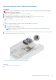
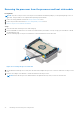

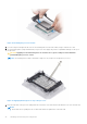
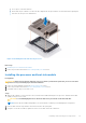

Table Of Contents
- Dell EMC PowerEdge MX840c Installation and Service Manual
- About this document
- Dell EMC PowerEdge MX840c overview
- Initial system setup and configuration
- Installing and removing sled components
- Safety instructions
- Before working inside your sled
- After working inside your sled
- Recommended tools
- PowerEdge MX840c sled
- Sled cover
- Air shroud
- Processor expansion module
- Drives
- Drive backplane
- Cable routing
- Drive cage
- Battery backup unit
- Control panel
- System memory
- Processors and heat sinks
- iDRAC card
- PERC cards
- Optional Internal dual SD module
- M.2 BOSS module
- Mezzanine card
- Optional internal USB memory key
- System battery
- System board
- Trusted Platform Module
- Jumpers and connectors
- System diagnostics and indicator codes
- Getting help
- Documentation resources

Figure 57. Removing the processor bracket
Next steps
1. Install the processor into the processor and heat sink module.
Installing the processor into a processor and heat sink module
Prerequisites
1. Follow the safety guidelines listed in the Safety instructions section.
2. Follow the procedure listed in the Before working inside your sled section.
Steps
1. Place the processor in the processor tray.
NOTE: Ensure that the pin 1 indicator on the processor tray is aligned with the pin 1 indicator on the processor.
2. Flex the outer edges of the bracket around the processor ensuring that the processor is locked into the clips on the bracket.
NOTE:
Ensure that the pin 1 indicator on the bracket is aligned with the pin 1 indicator on the processor before placing
the bracket on the processor.
NOTE: Ensure that the processor and the bracket are placed in the tray before you install the heat sink.
Installing and removing sled components 67