
Owners Manual
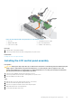
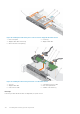
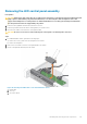
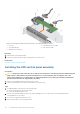
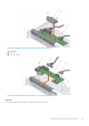
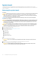
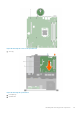
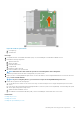

Figure 79. Removing the LED control panel board—four cabled hard drive chassis
1.
screw (2) 2. control panel connector cable
3. control panel board 4. USB connector cable
5. standoff on the chassis (2)
Next steps
1. Install the LED control panel assembly.
2. Follow the procedure listed in the After working inside your system section.
Related tasks
Installing the LED control panel assembly
Installing the LED control panel assembly
Prerequisites
CAUTION:
Many repairs may only be done by a certified service technician. You should only perform troubleshooting and
simple repairs as authorized in your product documentation, or as directed by the online or telephone service and
support team. Damage due to servicing that is not authorized by Dell is not covered by your warranty. Read and follow
the safety instructions that are shipped with your product.
1. Follow the safety guidelines listed in safety instructions section.
2. Follow the procedure listed in the Before working inside your system section.
Steps
1. For cabled hard drive systems, perform the following steps:
a) Insert the LED panel into the slot in the chassis.
b) Secure the LED panel with the screws.
2. Insert the control panel board into the slot in the chassis and align the two screw holes on the control panel board with the
corresponding holes on the chassis.
3. Secure the control panel board with the screws.
4. Connect all the cables to the control panel board.
114
Installing and removing system components