
Owners Manual
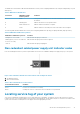

Back panel features and indicators
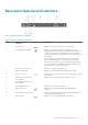
Figure 6. Back panel features and indicators
Table 5. Back panel features and indicators
Item Indicator, button, or
connector
Icon Description
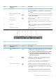
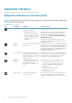
1 Serial connector Enables you to connect a serial device to the system.
2 System identification button Enables you to locate a particular system within a rack. The
identification buttons are on the front and back panels. When one
of these buttons is pressed, the LCD panel on the front and the
system status indicator on the back flash until one of the buttons is
pressed again.
Press the button to turn the system ID on or off. If the system
stops responding during POST, press and hold the system ID
button for more than five seconds to enter BIOS progress mode.
To reset the iDRAC (if not disabled in F2 iDRAC setup) press and
hold the button for more than 15 seconds.
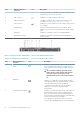
3 vFlash card slot (optional) Enables you to connect the vFlash card.
4 iDRAC port (optional) Enables you to install a dedicated management port card.
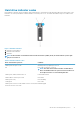
5 USB connectors (2) Enable you to connect USB devices to the system. The port is USB
3.0-compliant.
6 PCIe expansion card slot (x8
slot, low profile)
Enables you to connect a PCI Express expansion card.
7 PCIe expansion card slot (x16
slot, full height)
8 Power supply unit (PSU) Enables you to install one 250 W AC PSU.
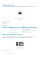
9 Ethernet connectors Enable you to connect integrated 10/100/1000 Mbps NIC
connector.
10 System identification connector Connects the optional system status indicator assembly through
the optional cable management arm.
11 Video connector Enables you to connect a VGA display to the system.
About the PowerEdge R230 systems 15