Dell PowerEdge R330 オーナーズマニュアル 規制モデル: E34S Series 規制タイプ: E34S001
メモ、注意、警告 メモ: 製品を使いやすくするための重要な情報を説明しています。 注意: ハードウェアの損傷やデータの損失の可能性を示し、その危険を回避するための方法を説明しています。 警告: 物的損害、けが、または死亡の原因となる可能性があることを示しています。 著作権 © 2017 すべての著作権は Dell Inc. またはその子会社にあります。 Dell、EMC、およびその他の商標は、Dell Inc. またはその 子会社の商標です。その他の商標は、それぞれの所有者の商標である場合があります。 2017 - 12 Rev.
目次 1 システムについて.......................................................................................................................... 8 PowerEdge R330 システムでサポートされる構成........................................................................................................9 前面パネルの機能とインジケータ.................................................................................................................................. 10 LCD パネルの機能................................................................................
ファームウェアとドライバをダウンロードする方法........................................................................................... 30 5 プレオペレーティングシステム管理アプリケーション...................................................................... 32 ナビゲーションキー........................................................................................................................................................... 32 セットアップユーティリティ.................................................................................................................
冷却エアフローカバー.......................................................................................................................................................58 冷却エアフローカバーの取り外し............................................................................................................................ 58 冷却エアフローカバーの取り付け............................................................................................................................ 59 システムメモリ.......................................................
オプションの SD vFlash カードの取り付け.......................................................................................................... 100 iDRAC ポートカード(オプション)............................................................................................................................ 100 オプションの iDRAC ポートカードの取り外し......................................................................................................101 オプションの iDRAC ポートカードの取り付け..........................................................................
システム基板のジャンパ設定........................................................................................................................................148 システム基板のコネクタ................................................................................................................................................149 パスワードを忘れたとき................................................................................................................................................ 150 9 お使いの システムのトラブルシューティング.................
1 システムについて Dell PowerEdge R330 は、シングル ソケットのラック サーバであり、次のハードウェア構成をサポートしています。 コンポーネント 数量 プロセッサ サーバは、次の製品ファミリーのプロセッサーを 1 つサポートします。 • • • • • • インテル E3-1200 v5 または v6 シリーズ インテル Core i3 6100 シリーズ インテル Celeron G3900 シリーズ インテル Celeron G3930 インテル Pentium G4500 シリーズ インテル Pentium G4600 シリーズ メモリモジュール 最大 4 個の DIMM ハードドライブ 最大 8 台のハード ドライブまたは SSD(ソリッド ステート ドライブ) トピック: • • • • • 8 PowerEdge R330 システムでサポートされる構成 前面パネルの機能とインジケータ 背面パネルの機能とインジケータ 診断インジケータ お使いのシステムのサービスタグの位置 システムについて
PowerEdge R330 システムでサポートされる構成 図 1.
前面パネルの機能とインジケータ 図 2. 前面パネルの機能とインジケータ — 4 台のホットスワップ対応 3.5 インチハードドライブシャーシ 表 1. 前面パネルの機能とインジケータ — 4 台のホットスワップ対応 3.
アイテム インジケータ、ボタン、また はコネクタ アイコン 9 情報タグ 参照用のサービスタグ、NIC、MAC アドレスなどのシステム情報 を含みます。情報タグは引き出し式のラベルパネルです。 10 ハードドライブスロット 最大で 4 台のホットスワップ対応 3.5 インチハードドライブ、また はホットスワップ対応 2.5 インチハードドライブを 3.5 インチハ ードドライブアダプタに取り付けることができます。 11 光学ドライブスロット オプションの薄型 SATA DVD-ROM ドライブまたは DVD+/-RW ド ライブを取り付けることができます。 説明 図 3. 前面パネルの機能とインジケータ — 8 台のホットスワップ対応 2.5 インチハードドライブまたは SSD シャーシ 表 2. 前面パネルの機能とインジケータ — 8 台のホットスワップ対応 2.
アイテム インジケータ、ボタン、または アイコン コネクタ 説明 5 USB コネクタ USB デバイスをシステムに接続するときに使用します。ポー トは USB 2.0 対応です。 6 光学ドライブスロット オプションの薄型 SATA DVD-ROM ドライブまたは DVD+/RW ドライブを取り付けることができます。 7 LCD メニューボタン コントロールパネル LCD メニューの切り替えに使用します。 8 情報タグ 参照用のサービスタグ、NIC、MAC アドレスなどのシステム情 報を含みます。情報タグは引き出し式のラベルパネルです。 9 LCD パネル システム ID、ステータス情報、システムエラーメッセージが表 示されます。「LCD パネルの機能」を参照してください。 10 ビデオコネクタ VGA ディスプレイをシステムに接続できます。 11 ハードドライブスロット 最大 8 台のホットスワップ対応 2.5 インチハードドライブを取 り付けることができます。 図 4. 前面パネルの機能とインジケータ — 4 つの 3.
アイテム インジケータ、ボタン、または アイコン コネクタ 説明 iDRAC をリセットするには(F2 iDRAC セットアップで無効に設 定されていない場合)、ボタンを 15 秒以上長押しします。 4 ビデオコネクタ ディスプレイをシステムに接続するときに使用します。 5 診断インジケータ 点灯してエラーステータスを表示します。詳細については、「前 面パネルの診断インジケータ」を参照してください。 6 USB コネクタ USB デバイスをシステムに接続できます。ポートは USB 2.0 対 応です。 7 情報タグ 参照用のサービスタグ、NIC、MAC アドレスなどのシステム情 報を含みます。情報タグは引き出し式のラベルパネルです。 8 ハードドライブスロット 最大で 4 台の 3.5 インチケーブル接続ハードドライブを取り付 けることができます。 9 光学ドライブまたはソリッド ステートドライブ(SSD)スロ ット オプションの SATA DVD-ROM ドライブまたは DVD+/-RW ドラ イブ 1 台、またはオプションの 1.
背面パネルの機能とインジケータ 図 6. 背面パネルの機能とインジケータ 表 4. 背面パネルの機能とインジケータ アイテム インジケータ、ボタン、または アイコン コネクタ 説明 1 シリアルコネクタ シリアルデバイスをシステムに接続できます。 2 vFlash カードスロット(オプシ ョン) vFlash カードを接続できます。 3 iDRAC ポート(オプション) 専用管理ポートカードを取り付けることができます。 4 PCIe 拡張カードスロット(2) PCI Express 拡張カードを接続できます。 5 電源装置ユニット(PSU1 と PSU2) 350 W 冗長 AC 電源装置ユニットを 2 台まで取り付けることが できます。 6 USB コネクタ USB デバイスをシステムに接続できます。ポートは USB 3.
前面パネルの診断インジケータ メモ: システムの電源が切れているときは、どの診断インジケータも点灯しません。システムを起動するには、機能している電 源に接続してから電源ボタンを押します。 表 5. 診断インジケータ アイコン 説明 状態 対応処置 ヘルスインジケー システムが良好な状態である場合 不要。 タ は、インジケータが青色に点灯しま す。 次の場合はインジケータが橙色に点 特定の問題については、システムイベントログまたは 滅します。 システムメッセージを確認してください。エラーメッ セージの詳細については、Dell.
図 7. ハードドライブインジケータ 1. ハードドライブアクティビティインジケータ 2. ハードドライブステータスインジケータ 3. ハードドライブ メモ: ハードドライブが Advanced Host Controller Interface(AHCI)モードの場合、ステータスインジケータ(右側)は点灯 しません。 表 6.
図 8. NIC インジケータ 1. リンクインジケータ 2. アクティビティインジケータ 表 7.
iDRAC ダイレクト LED インジケータコード iDRAC ダイレクト LED インジケータが点灯して、ポートが接続され、iDRAC サブシステムの一部として使用されていることを示し ます。 メモ: USB ポートが USB モードで使用されている場合、iDRAC ダイレクト LED インジケータは点灯しません。 1. iDRAC ダイレクトステータスインジケータ iDRAC ダイレクト LED インジケータ表は、管理ポート(USB XML インポート)を使用して iDRAC ダイレクトを設定しているときの iDRAC ダイレクトのアクティビティを説明しています。 表 9.
図 9. AC PSU ステータスインジケータ 1. AC PSU ステータスインジケータまたはハンドル 表 11. 冗長 AC PSU ステータスインジケータ 表記規則 電源インジケータのパ 状態 ターン A 緑色 有効な電源が PSU に接続されているか、PSU が動作中です。 B 緑色の点滅 PSU ファームウェアのアップデート中に、PSU ハンドルが緑色に点滅します。 注意: ファームウェアをアップデートしている際に、電源コードを外したり PSU を抜いたりしないでください。ファームウェアのアップデートが中断した場合、 PSU は機能しなくなります。Dell Lifecycle Controller を使用して PSU ファー ムウェアをロールバックする必要があります。Dell.
表記規則 電源インジケータのパ 状態 ターン E 消灯 電源が接続されていません。 お使いのシステムのサービスタグの位置 お使いのシステムは一意のエクスプレスサービスコードおよびサービスタグ番号によって識別されます。エクスプレスサービスコ ードおよびサービスタグは、システムの前面、で情報タグを引き出して確認します。または、システムのシャーシに貼られたステッ カーに情報が記載されている場合があります。この情報は、デルが電話によるサポートのお問い合わせを適切な担当者に転送する ために使用されます。 お使いのシステムは一意のエクスプレスサービスコードおよびサービスタグ番号によって識別されます。エクスプレスサービスコ ードおよびサービスタグは、システムの前面で情報タグを引き出して確認します。または、システムのシャーシに貼られたステッ カーに情報が記載されている場合があります。この情報は、デルが電話によるサポートのお問い合わせを適切な担当者に転送する ために使用されます。 20 システムについて
2 マニュアルリソース 本項では、お使いのシステムのマニュアルリソースに関する情報を提供します。 表 12. お使いのシステムのためのその他マニュアルのリソース タスク 文書 システムのセットアップ システムをラックに取り付けて固定する方法の Dell.com/poweredgemanuals 詳細については、お使いのラックソリューション に同梱のラックマニュアルを参照してくださ い。 システムのセットアップと電源投入に関する情 報については、お使いのシステムに付属する 『Getting Started Guide』(はじめに)マニュアル を参照してください。 システムの設定 場所 Dell.com/poweredgemanuals iDRAC 機能、iDRAC の設定と iDRAC へのログイ Dell.
タスク 文書 場所 Enterprise ユーザーズガイド)を参照してくださ い。 Dell Lifecycle Controller の機能を把握するには、 Dell.com/idracmanuals 『Dell Lifecycle Controller User’s Guide』(Dell Lifecycle Controller ユーザーズガイド)を参照し てください。 パートナープログラムのエンタープライズシス テム管理についての情報は、OpenManage Connections Enterprise Systems Management マ ニュアルを参照してください。 Dell PowerEdge RAID コント ローラの操作 Dell.com/openmanagemanuals Dell PowerEdge RAID コントローラ(PERC)、ソ Dell.
3 技術仕様 シャーシ寸法 本項では、システムの物理的寸法について説明します。 図 10. PowerEdge R330 システムのシャーシ寸法 表 13. Dell PowerEdge R330 システムの寸法 X 482.4 mm (18.99 イン チ) Xa 434.0 mm (17.08 イン チ) はい Z(ベゼルを含 Z(ベゼルを含 Za(ベゼルを む) まない) 含む) 42.4 mm(1.66 681.2 mm インチ) (26.81 イン チ) 666.2 mm (26.22 イン チ) Za(ベゼルを 含まない) 35.1 mm(1.38 20.1 mm インチ) Zb 607.0 mm (23.89 イン チ) シャーシの重量 本項では、システムの重量について説明します。 表 14. シャーシの重量 システム 最大重量(すべてのハードドライブ /SSD を含む) PowerEdge R330 26.02 kg(30.
プロセッサの仕様 プロセッサ 仕様 タイプ PowerEdge R330 は、次に示すどのプロセッサーもサポートしています。 • • • • • • インテル E3-1200 v5 または v6 シリーズ インテル Core i3 6100 シリーズ インテル Celeron G3900 シリーズ インテル Celeron G3930 インテル Pentium G4500 シリーズ インテル Pentium G4600 シリーズ 拡張バスの仕様 仕様 PCI Express (PCIe) Generation 3 拡張スロット (オプションの 拡張カードライ ザー搭載) LP スロット 1 ハーフハイト、ハーフレングスの x4 リンク(1) FH スロット 2 フルハイト、ハーフレングスの x8 リンク(1) PCI Express Generation 3 拡張スロット (拡張カードラ イザーなし) 仕様 PCIE_G3_X4 PERC カード用ハーフハイト、ハーフレングスの x4 リンク(1) PCIE_G3_X8 ライザー用 x8 リンク(1) メモリの仕様 メモリ 仕様
電源仕様 電源装置ユニッ 仕様 ト 電源装置ユニット あたり電力定格 350 W(プラチナ)(100~240 V AC、50/60 Hz、4.8~2.4 A) 熱消費 1357.1 BTU/ 時 メモ: 熱放散は電源のワット数定格に基づいて算出されています。 電圧 100~240 VAC、自動選択、50/60 Hz メモ: このシステムは、線間電圧が 230 V 以下の IT 電力システムに接続できるようにも設計されていま す。 ストレージコントローラの仕様 ストレージコン 仕様 トローラ ストレージコント ローラのタイプ PERC H730、PERC H330、PERC H830、PERC S130 メモ: お使いのシステムでは、ソフトウェア RAID S 130 および PERC カードがサポートされています。 ソフトウェア RAID に関する詳細については、Dell.
ポートおよびコネクタの仕様 USB ポート PowerEdge R330 システムは次をサポートしています。 • • • 前面パネルの USB 2.0 対応ポート 背面パネルの USB 3.0 対応ポート USB 3.0 対応内蔵ポート 次の表には、USB の仕様についての詳細が記載されています。 表 15. USB の仕様 システム 前面パネル 背面パネル 内蔵 PowerEdge R330 4 ピン USB 2.0 対応ポート(2) 9 ピン USB 3.0 対応ポート(2) 9 ピン USB 3.
表 16. サポートされているビデオ解像度のオプション 解像度 リフレッシュレート (Hz) 色深度(ビット) 640 x 480 60、70 8、16、24 800 x 600 60、75、85 8、16、24 1024 x 768 60、75、85 8、16、24 1152 x 864 60、75、85 8、16、24 1280 x 1024 60、75 8、16、24 動作時の拡張温度 メモ: 動作時の拡張温度範囲で使用すると、システムのパフォーマンスに影響が生じる場合があります。 メモ: 拡張温度範囲でシステムを使用している際に、LCD とシステムイベントログに周囲温度の警告が報告される場合があり ます。 動作時の拡張温 仕様 度 継続動作 相対湿度 5~85%、露点温度 29°C(84.2°F)で、5~40°C(40~104°F)。 メモ: 標準動作温度(10~35°C、50~95°F)の範囲外で使用する場合、システムは 5~40°C(40~ 104°F)の範囲で継続動作が可能です。 35~40°C(95~104°F)の場合、950 m(3116.
相対湿度 仕様 ストレージ 最大露点 33 °C(91 °F)で 5~95 % の相対湿度。空気は常に非結露状態であること。 動作時 最大露点 29°C(84.2°F)で 10~80% の相対湿度。 最大耐久震度 仕様 動作時 0.26 Grms(5~350 Hz)(全稼働方向)。 ストレージ 1.88 Grms (10~500 Hz) で 15 分間(全 6 面で検証済)。 最大耐久衝撃 仕様 動作時 x、y、z 軸の正および負方向に 6 連続衝撃パルス、2.3 ミリ秒以下で 40 G、。 ストレージ x、y、z 軸の正および負方向に 6 連続衝撃パルス(システムの各面に対して 1 パルス)、2 ミリ秒以下で 71 G。 最大高度 仕様 動作時 30482000 m(10,0006560 フィート)。 ストレージ 12,000 m(39,370 フィート)。 動作時温度ディ 仕様 レーティング 最高 35 °C(95 °F) 950 m(3,117 フィート)を越える高度では、最高温度は 300 m(984.25 フィート)ごとに 1°C(33.
4 システムの初期セットアップと設定 システムのセットアップ 次の手順を実行して、システムを設定します。 手順 1. システムを開梱します。 2. システムをラックに取り付けます。ラックへのシステムの取り付けの詳細については、システムの「ラック取り付けプレースマ ット」(Dell.com/poweredgemanuals)を参照してください。 3. 周辺機器をシステムに接続します。 4. システムを電源コンセントに接続します。 5. 電源ボタンを押す、または iDRAC を使用してシステムの電源を入れます。 6.
デフォルトのユーザー名とパスワードは、root と calvin です。シングルサインオンまたはスマートカードを使用してログインす ることもできます。 メモ: iDRAC にログインするには、iDRAC 資格情報が必要です。 iDRAC へのログイン、および iDRAC ライセンスの詳細については、Dell.com/idracmanuals で最新の『Integrated Dell Remote Access Controller User's Guide』(Integrated Dell Remote Access Controller ユーザーズガイド)を参照してください。 オペレーティングシステムをインストールするオプ ション システムがオペレーティングシステムのインストールなしで出荷された場合、次のリソースのいずれかを使用して対応するオペレー ティングシステムをインストールします。 表 17. オペレーティングシステムをインストールするリソース リソースを見つける 場所 Dell Systems Management Tools and Documentation メディア Dell.
メモ: サービスタグがない場合は、Detect My Product(製品の検出)を選択してシステムにサービスタグを自動的に検出 させるか、製品サポートでお使いの製品を選択します。 3. Drivers & Downloads(ドライバおよびダウンロード)をクリックします。 ユーザーの選択した項目に該当するドライバが表示されます。 4.
5 プレオペレーティングシステム管理アプリケー ション システムのファームウェアを使用して、オペレーティングシステムを起動せずにシステムの基本的な設定や機能を管理することが できます。 トピック: • • • • • • • • • • • • ナビゲーションキー セットアップユーティリティ 起動マネージャについて Dell Lifecycle Controller の概要 起動順序の変更 システム起動モードの選択 システムパスワードおよびセットアップパスワードの作成 システムを保護するためのシステムパスワードの使用 システムパスワードおよびセットアップパスワードの削除または変更 セットアップパスワード使用中の操作 組み込み型システム管理 iDRAC 設定ユーティリティ ナビゲーションキー ナビゲーションキーは、プリオペレーティングシステム管理アプリケーションへのクイックアクセスに便利です。 表 19.
• • 標準グラフィカルブラウザ — デフォルトでは有効になっています。 テキストブラウザ — コンソールリダイレクトの使用によって有効になります。 セットアップユーティリティの起動 手順 1. システムの電源を入れるか、または再起動します。 2.
オプション 説明 Integrated Devices 内蔵デバイスコントローラとポートの管理、および関連する機能とオプションの指定を行うオプションを指 (内蔵デバイス) 定します。 Serial Communication (シリアル通信) シリアルポートの管理、および関連する機能とオプションの指定を行うオプションを指定します。 System Profile プロセッサの電力管理設定、メモリ周波数などを変更するオプションを指定します。 Settings(システム プロファイル設定) System Security システムパスワード、セットアップパスワード、Trusted Platform Module(TPM)セキュリティなどのシステ (システムセキュリ ムセキュリティ設定を行うオプションを指定します。システムの電源ボタンや NMI ボタンもこれで管理し ティ) ます。 Miscellaneous システムの日時などを変更するオプションを指定します。 Settings(その他の 設定) システム情報の詳細 このタスクについて System Information(システム情報画面)の詳細は、次の
メモリ設定の詳細 このタスクについて Memory Settings(メモリ設定)画面の詳細は、次のとおりです。 オプション 説明 System Memory システム内のメモリサイズを指定します。 Size(システムメモ リのサイズ) System Memory システムに取り付けられているメモリのタイプを指定します。 Type(システムメモ リのタイプ) System Memory メモリの速度を指定します。 Speed(システムメ モリ速度) System Memory メモリの電圧を指定します。 Voltage(システム メモリ電圧) Video Memory(ビ ビデオメモリの容量を指定します。 デオメモリ) System Memory システム起動時にメモリテストを実行するかどうかを指定します。オプションは Enabled(有効)および Testing(システム Disabled(無効)です。このオプションは、デフォルトで Disabled(無効)に設定されています。 メモリテスト) Memory Operating メモリの動作モードを指定します。使用可能なオプションは、Optimizer
オプション 説明 ストリーマプリフ ェッチャ) DCU IP Prefetcher データキャッシュユニット(DCU)IP プリフェッチャーの有効 / 無効を切り替えます。このオプションは、 (DCU IP プリフェ デフォルトで Enabled(有効)に設定されています。 ッチャ) Configurable TDP (設定可能 TDP) システムの電力および温度送出機能に基づいて、POST 中にプロセッサの熱設計電力(TDP)のレベルを再 設定することができます。TDP は冷却システムが熱分散に必要な最大熱量を確認します。このオプション は、デフォルトで Nominal(公称)に設定されています。 メモ: このオプションは、プロセッサの特定の最小在庫管理単位(SKUs)でのみ利用可能です。 X2Apic Mode (X2Apic モード) Dell Controlled Turbo X2Apic モードを有効または無効にします。 ターボエンゲージメントを制御します。このオプションは、System Profile(システムプロファイル)が Performance(パフォーマンス)に設定されている場合
オプション 説明 Security Freeze POST 中に組み込み SATA ドライブにセキュリティフリーズロックコマンドを送信します。このオプション Lock(セキュリティ は、AHCI モードにのみ適用されます。 フリーズロック) Write Cache(書き POST 中に組み込み SATA ドライブの コマンドを有効または無効にします。 込みキャッシュ) Port A(ポート A) AHCI または RAID モードの場合、BIOS のサポートは常に有効です。 オプション 説明 Model(モデル) 選択されたデバイスのドライブモデルを指定します。 Drive Type(ドライ SATA ポートに接続されているドライブのタイプを指定します。 ブタイプ) Capacity(容量) ハードドライブの合計容量を指定します。オプティカルドライブなどのリムーバブル メディアデバイスに対しては未定義です。 Port B(ポート B) AHCI または RAID モードの場合、BIOS のサポートは常に有効です。 オプション 説明 Model(モデル) 選択されたデバイスのドライブモ
オプション 説明 Port F(ポート F) 選択されたデバイスのドライブタイプを設定します。Embedded SATA settings(組み込み SATA 設定)が ATA モードに設定されている場合、BIOS サポートを有効にするには、このフィールドを Auto(自動)に設 定する必要があります。BIOS サポートをオフにするには、OFF(オフ)に設定します。 AHCI または RAID モードの場合、BIOS のサポートは常に有効です。 オプション 説明 Model(モデル) 選択されたデバイスのドライブモデルを指定します。 Drive Type(ドライ SATA ポートに接続されているドライブのタイプを指定します。 ブタイプ) Capacity(容量) ハードドライブの合計容量を指定します。オプティカルドライブなどのリムーバブル メディアデバイスに対しては未定義です。 起動設定の詳細 このタスクについて Boot Settings(起動設定)画面の詳細は、次のとおりです。 オプション 説明 Boot Mode(起動 モード) システムの起動モードを設定できます。 注意: オ
このタスクについて オプション 説明 PXE Device n(PXE デバイスを有効または無効にします。有効にすると、デバイスの UEFI 起動オプションが作成されます。 デバイス n)(n = 1 ~4) PXE Device n PXE デバイスの設定を制御できます。 Settings(PXE デバ イス n 設定)(n = 1 ~4) UEFI iSCSI 設定画面の詳細 UEFI iSCSI 設定画面を使用して、iSCSI デバイスの設定を変更できます。 iSCSI 設定オプションは UEFI 起動モードでのみ使用可能で す。BIOS 起動モードでは、BIOS はネットワーク設定の制御を行いません。BIOS 起動モードの場合は、ネットワークコントローラの オプション ROM でネットワーク設定を処理します。 UEFI iSCSI 設定画面を表示するには、System Setup Main Menu(セットアップユーティリティメインメニュー) > System BIOS (システム BIOS) > Network Settings(ネットワーク設定) > UEFI iSCSI Settings
オプション 説明 ワークカード 1 オプションと同時に指定することはできません。Embedded NIC1 and NIC2(内蔵 NIC1 および NIC2)オプションは、システムの NIC 管理ユーティリティを使用して設定します。 I/O Snoop Holdoff のサイクル数を PCI I/O 、 CPU から snoop リクエスト、そのを独自の LLC の書き込みが完了する時間を許 Response(I/O ス 可することができます剥奪を選択します。この設定では、スループットを向上させ、レイテンシが重要な作 ヌープレスポンス 業負荷でのパフォーマンスが向上できます。 の先送り) Embedded Video Embedded Video Controller(内蔵ビデオコントローラ)オプションを有効または無効にします。このオプ Controller(内蔵ビ ションは、デフォルトで Enabled(有効)に設定されています。 デオコントローラ) Current State of Embedded Video Controller(内蔵ビ デオコントローラ の現在の状態) 内蔵ビデオコントローラ
オプション 説明 メモ: SOL には Serial Device 2(シリアルデバイス 2)のみ使用できます。SOL でコンソールのリダイ レクトを使用するには、コンソールのリダイレクトとシリアルデバイスに同じポートアドレスを設定し ます。 メモ: システムを起動するたびに、BIOS は iDRAC で保存された設定でシリアル MUX を同期します。 シリアル MUX 設定は、iDRAC で個別に変更できます。したがって、BIOS セットアップユーティリテ ィから BIOS のデフォルト設定をロードしても、この設定がシリアルデバイス 1 のデフォルト設定に戻 らない場合があります。 Failsafe Baud Rate コンソールのリダイレクトに使用されているフェイルセーフボーレートが表示されます。BIOS は自動的にボ (フェイルセーフボ ーレートの決定を試みます。このフェイルセーフボーレートは、その試みが失敗した場合にのみ使用されま ーレート) す。また、値は変更しないでください。デフォルトでは、このオプションは 115200 に設定されています。 Remote Terminal リモートコンソール
オプション 説明 Energy Efficient Policy(省エネル ギーポリシー) Energy Efficient Policy(省エネルギーポリシー)オプションを選択することが可能になります。 Number of Turbo Boost Enabled Cores for Processor 1(プロ セッサ 1 のターボ ブースト対応コア 数) プロセッサ 1 のターボブースト対応コア数を制御します。コアの最大数がデフォルトで有効にします。 Monitor/Mwait プロセッサ内の Monitor/Mwait 命令を有効にします。このオプションは、デフォルトで Custom(カスタ ム)以外のすべてのシステムプロファイルに対して Enabled(有効)に設定されています。 メモ: このオプションは、Custom(カスタム)モードの C States(C ステート) オプションが Disabled (無効)に設定されている場合に限り、無効に設定できます。 CPU はプロセッサの内部動作を操作するための設定を使用して、より高いパフォーマンスを求めるか、それ ともより良い省電力を求め
オプション 説明 電源ボタン システム前面の電源ボタンを有効または無効にします。このオプションは、デフォルトで Enabled(有効) に設定されています。 NMI ボタン システム前面の NMI ボタンを有効または無効にします。このオプションは、デフォルトで Disabled(無効) に設定されています。 AC 電源リカバリ システムの AC 電源が回復した後のシステムの動作を設定します。このオプションは、デフォルトで Last (前回)に設定されています。 AC 電源リカバリ遅 システムの AC 電源が回復した後のシステムへの電源投入の時間遅延を設定します。このオプションは、デ 延 フォルトで Immediate(即時)に設定されています。 ユーザー定義遅延 (60 ~ 240 秒) AC Power Recovery Delay(AC 電源リカバリ遅延)に User Defined(ユーザー定義)オプションが選択さ れている場合、User Defined Delay(ユーザー定義の遅延)オプションを設定します。 UEFI 変数アクセス UEFI 変数を安全に維持するためのさまざまな手
オプション 説明 システム時刻 システムの時刻を設定することができます。 システム日付 システムの日付を設定することができます。 資産タグ 資産タグを指定して、セキュリティと追跡のために変更することができます。 キーボード NumLock NumLock が有効または無効のどちらの状態でシステムが起動するかを設定できます。デフォルトでは、この オプションは On(オン)に設定されています。 メモ: このフィールドは 84 キーのキーボードには適用されません。 エラー時 F1/F2 プ ロンプト エラー時の F1/F2 プロンプトを有効または無効にします。このオプションは、デフォルトで Enabled(有効) に設定されています。F1/F2 プロンプトは、キーボードエラーも含みます。 レガシービデオオ プション ROM の ロード システム BIOS でビデオコントローラからレガシービデオ(INT 10H)オプション ROM をロードするかどうか を決定できます。オペレーティングシステムで Enabled(有効)を選択すると、UEFI ビデオ出力標準をサ ポートしません。このフィールド
メニュー項目 説明 One Shot Boot 起動メニューにアクセスし、ワンタイム起動デバイスを選択して、このデバイスから起動できます。 Menu(ワンショッ ト起動メニュー) Launch System セットアップユーティリティにアクセスできます。 Setup(セットアッ プユーティリティ の起動) Launch Lifecycle 起動マネージャを終了し、Dell Lifecycle Controller プログラムを起動します。 Controller (Lifecycle Controller の起動) System Utilities (システムユーティ リティ) システム診断および UEFI シェルなどのシステムユーティリティメニューを起動できます。 Dell Lifecycle Controller の概要 Dell Lifecycle Controller で、BIOS およびハードウェアの設定、オペレーティングシステムの導入、ドライバのアップデート、RAID 設 定の変更、ハードウェアプロファイルの保存などのタスクを実行できます。Dell Lifecycle Controller
システムパスワードおよびセットアップパスワード の作成 前提条件 パスワードジャンパが有効になっているようにします。パスワードジャンパによって、システムパスワードとセットアップパスワー ドの機能を有効または無効にすることができます。詳細については、「システム基板のジャンパ設定」の項を参照してください。 メモ: パスワードジャンパの設定を無効にすると、既存のシステムパスワードとセットアップパスワードは削除され、システム の起動にシステムパスワードを入力する必要がなくなります。 手順 1. セットアップユーティリティを起動するには、システムの電源投入または再起動の直後に F2 を押します。 2. System Setup Main Menu(セットアップユーティリティメインメニュー) 画面で、System BIOS(システム BIOS) > System Security(システムセキュリティ) の順にクリックします。 3.
必要があることを示すメッセージが、システムによって表示されます。システムの電源を切って再起動しても、正しいパスワ ードを入力するまで、このエラーメッセージが表示されます。 システムパスワードおよびセットアップパスワード の削除または変更 前提条件 パスワードジャンパが Enabled(有効)に設定され、Password Status(パスワードステータス)が Unlocked(ロック解除)され ていることを確認してから、既存のシステムパスワードまたはセットアップパスワードを削除または変更します。 メモ: Password Status(パスワードステータス)が Locked(ロック)されている場合は、既存のシステムパスワードまたは セットアップパスワードを削除または変更できません。 手順 1. セットアップユーティリティを起動するには、システムの電源投入または再起動の直後に F2 を押します。 2.
組み込み型システム管理 Dell Lifecycle Controller により、システムのライフサイクル全体を通して、高度な組み込み型システムを管理できるようになりま す。Dell Lifecycle Controller は起動時にも開始することができ、オペレーティングシステムに依存せずに機能します。 メモ: 一部のプラットフォーム構成では、Dell Lifecycle Controller の提供する機能の一部がサポートされない場合があります。 Dell Lifecycle Controller のセットアップ、ハードウェアとファームウェアの設定、およびオペレーティングシステムの導入の詳細に ついては、Dell.
6 システムコンポーネントの取り付けと取り外し 安全にお使いいただくために メモ: システムを持ち上げる必要のある場合は、必ず 2 人以上で行ってください。けがを防ぐために、決してシステムを 1 人 で持ち上げようとしないでください。 警告: システムの電源が入っている状態でシステムカバーを開いたり取り外したりすると、感電するおそれがあります。 注意: システムは、カバー無しで 5 分以上動作させないでください。 注意: 修理作業の多くは、認定されたサービス技術者のみが行うことができます。製品マニュアルで許可されている範囲に限 り、またはオンラインサービスもしくは電話サービスとサポートチームの指示によってのみ、トラブルシューティングと簡単な 修理を行うようにしてください。Dell の許可を受けていない保守による損傷は、保証の対象となりません。製品に付属する 「安全にお使いいただくために」をよく読み、指示に従ってください。 メモ: システム内部のコンポーネントでの作業中は、常に静電マットと静電ストラップを使用することをお勧めします。 メモ: 正常な動作と冷却を確保するため、システム内のすべてのベイおよびシステム
5. システムとすべての周辺機器の電源を入れます。 関連タスク オプションの前面ベゼルの取り付け システムカバーの取り付け 推奨ツール 取り外しと取り付け手順を実行するには、以下のツールが必要になります。 • • • #2 プラスドライバ プラスチックスクライブ アースされた静電気防止用リストバンド 前面ベゼル(オプション) 前面ベゼルはシステムの前面に取り付けてあり、ハードドライブの取り外し中、またはリセットボタンや電源ボタンを押したとき の事故を防止します。前面ベゼルは、セキュリティ強化のためにロックすることもできます。 オプションの前面ベゼルの取り外し 前提条件 「安全にお使いいただくために」の項に記載された安全ガイドラインに従ってください。 手順 1. ベゼルの左端のキーロックを解除します。 2. キーロックの横にあるリリースラッチを押し上げます。 3. ベゼルの左端を前面パネルと反対の方向へ動かします。 4. ベゼル右端のフックを外し、ベゼルをシステムから取り外します。 図 11. オプションの前面ベゼルの取り外し a. ベゼルロック b.
オプションの前面ベゼルの取り付け 前提条件 「安全にお使いいただくために」の項に記載された安全ガイドラインに従ってください。 手順 1. ベゼルキーの位置を確認して取り外します。 メモ: ベゼルキーはベゼルの背面に取り付けられています。 2. ベゼルの右端をシャーシに取り付けます。 3. ベゼルのもう一方の端をシステムにはめ込みます。 4. キーを使用してベゼルをロックします。 図 12. オプションの前面ベゼルの取り付け a. ロック b. 前面ベゼル システムカバー システムカバーの取り外し 前提条件 1. 2. 3. 4. 「安全にお使いいただくために」を必ずお読みください。 システムとすべての周辺機器の電源を切ります。 システムを電源コンセントと周辺機器から外します。 前面ベゼルが取り付けられている場合は、取り外します。 手順 1. ラッチリリースロックをロック解除位置に回します。 2. ラッチを持ち上げ、そのラッチをシステムの後方に回転させます。 システムカバーを後方にスライドさせ、システムカバーのタブをシャーシのスロットにから外します。 3.
図 13. システムカバーの取り外し a. ラッチリリースロック b. ラッチ c. システムカバー 次の手順 システムカバーを取り付けます。 関連タスク オプションの前面ベゼルの取り外し システムカバーの取り付け システムカバーの取り付け 前提条件 1. 「安全にお使いいただくために」の項に記載された安全ガイドラインに従ってください。 2. 「システム内部の作業を始める前に」の項に記載された手順に従います。 3. すべての内部ケーブルが接続され、邪魔にならないように束ねられており、システム内部に工具や余分な部品が残っていないこ とを確認します。 手順 1. システムカバーのスロットをシャーシのタブに合わせます。 2. システムカバーのラッチを押し下げます。 システムカバーを前方にスライドさせると、システムカバーのスロットがシャーシのタブにはめ込まれます。システムカバーが シャーシのタブに完全にはめ込まれると、システムカバーラッチが所定の位置にロックされます。 3.
図 14. システムカバーの取り付け a. ラッチリリースロック b. ラッチ c. システムカバー 次の手順 1. 2. 3. 4.
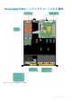
システムの内部 図 15. システムの内部 — 4 台のホットスワップ対応 3.5 インチハードドライブ 1. 3. 5. 7. 9. 11. 54 ハードドライブバックプレーン 電源装置ユニット(2) メモリモジュールソケット システム基板 イントルージョンスイッチ 光学ドライブ(オプション) システムコンポーネントの取り付けと取り外し 2. 4. 6. 8. 10. 12.
図 16. システムの内部 - 8 台の 2.5 インチハードドライブ 1. 3. 5. 7. 9. 11. 光学ドライブ(オプション) 電源インタポーザボード 拡張カードライザー プロセッサ 冷却ファン(4) ハードドライブ(8) 2. 4. 6. 8. 10. 12.
図 17. システムの内部 — 4 台の 3.5 インチケーブル接続式ハードドライブ 1. 3. 5. 7. 9. ハードドライブ(4) 電源装置ユニット(2) メモリモジュールソケット(4) システム基板 イントルージョンスイッチ 2. 4. 6. 8. 10. 電源インタポーザボード 拡張カードライザー プロセッサ 冷却ファン(4) オプションの光学ドライブ、または 1.8 インチソリッドステー トドライブ(オプション) 11.
1. 「安全にお使いいただくために」の項に記載された安全ガイドラインに従ってください。 2. 「システム内部の作業を始める前に」の項に記載された手順に従います。 3. プラスチックスクライブを準備しておきます。 手順 1. システム基板上のコネクタからイントルージョンスイッチケーブルを外します。 2. ケーブル配線ラッチからケーブルを外します。 3. プラスチックスクライブを使って、イントルージョンスイッチをスライドさせ、イントルージョンスイッチスロットの下から取 り外します。 図 18. イントルージョンスイッチの取り外し 1. イントルージョンスイッチ 3. イントルージョンスイッチケーブル 5. ケーブル配線クリップ 2. イントルージョンスイッチスロット 4. システム基板のイントルージョンスイッチコネクタ 次の手順 1. イントルージョンスイッチを取り付けます。 2.
2. 「システム内部の作業を始める前に」の項に記載された手順に従います。 手順 1. イントルージョンスイッチをイントルージョンスイッチスロットに差し込みます。 2. イントルージョンスイッチが所定の位置にロックされるまでスライドさせます。 3. ルートイントルージョンスイッチケーブルを、ケーブル配線タブに通して配線します。 4. イントルージョンスイッチケーブルをシステム基板上のコネクタに接続します。 図 19. イントルージョンスイッチの取り付け 次の手順 1.
手順 エアフローカバーを持ち上げて、システムから取り外します。 図 20. 冷却エアフローカバーの取り外し a. 冷却エアフローカバー b. 冷却エアフローカバーのガイド c. シャーシ壁面のガイドピン 次の手順 1. 冷却エアフローカバーを取り付けます。 2. 「システム内部の作業を終えた後に」の手順に従ってください。 関連タスク 冷却エアフローカバーの取り付け 冷却エアフローカバーの取り付け 前提条件 注意: 修理作業の多くは、認定されたサービス技術者のみが行うことができます。製品マニュアルで許可されている範囲に限 り、またはオンラインサービスもしくは電話サービスとサポートチームの指示によってのみ、トラブルシューティングと簡単な 修理を行うようにしてください。Dell の許可を受けていない保守による損傷は、保証の対象となりません。製品に付属する 「安全にお使いいただくために」をよく読み、指示に従ってください。 1. 「安全にお使いいただくために」を必ずお読みください。 2. 「システム内部の作業を始める前に」の手順に従ってください。 手順 1.
図 21. 冷却エアフローカバーの取り付け a. 冷却エアフローカバー b. 冷却エアフローカバーのガイド c.
図 22. システム基板上のメモリソケットの位置 メモリチャネルは次のように構成されます。 Processor 1(プロ セッサ 1) チャネル 0:メモリソケット A1 と A3 チャネル 1:メモリソケット A2 と A4 次の表は、サポートされている構成のメモリ装着と動作周波数を示しています。 表 20. サポートされている構成のメモリ装着と動作周波数。 メモリモジュールのタイプ 各チャネルに装着され ているメモリモジュー ル 動作周波数(単位:MT/s) チャネルごとの最大メモリモジュ ールのランク 1.
メモリ構成の例 次の表は、シングルプロセッサ構成用のメモリの構成例を示しています。 メモ: 次の表の 1R と 2R はそれぞれ、シングルランクとデュアルランクのメモリモジュールを示しています。 表 21.
メモリモジュールの取り外し 前提条件 注意: 修理作業の多くは、認定されたサービス技術者のみが行うことができます。製品マニュアルで許可されている範囲に限 り、またはオンラインサービスもしくは電話サービスとサポートチームの指示によってのみ、トラブルシューティングと簡単な 修理を行うようにしてください。Dell の許可を受けていない保守による損傷は、保証の対象となりません。製品に付属する 「安全にお使いいただくために」をよく読み、指示に従ってください。 1. 「安全にお使いいただくために」を必ずお読みください。 2. 「システム内部の作業を始める前に」の手順に従ってください。 3. 冷却用エアフローカバーを取り外します。 メモ: メモリモジュールは、システムの電源を切った後もしばらくは触れられないほど高温です。メモリモジュールの冷却を 待ってから作業してください。メモリモジュールはカードの両端を持ち、メモリモジュールのコンポーネントや金属の接触部 には指を触れないでください。 手順 1. 該当するメモリモジュールソケットの位置を確認します。 2.
関連タスク メモリモジュールの取り付け 冷却エアフローカバーの取り外し 冷却エアフローカバーの取り付け メモリモジュールの取り付け 前提条件 注意: 修理作業の多くは、認定されたサービス技術者のみが行うことができます。製品マニュアルで許可されている範囲に限 り、またはオンラインサービスもしくは電話サービスとサポートチームの指示によってのみ、トラブルシューティングと簡単な 修理を行うようにしてください。Dell の許可を受けていない保守による損傷は、保証の対象となりません。製品に付属する 「安全にお使いいただくために」をよく読み、指示に従ってください。 1. 「安全にお使いいただくために」を必ずお読みください。 2. 「システム内部の作業を始める前に」の手順に従ってください。 3. 冷却用エアフローカバーを取り外します。 メモ: メモリモジュールは、システムの電源を切った後もしばらくは触れられないほど高温です。メモリモジュールの冷却を 待ってから作業してください。メモリモジュールはカードの両端を持ち、メモリモジュールのコンポーネントや金属の接触部 には指を触れないでください。 手順 1.
図 24. メモリモジュールの取り付け a. メモリモジュール b. 位置合わせキー c. メモリモジュールソケットのイジェクタ(2) 次の手順 1. 冷却用エアフローカバーを取り付けます。 2. システム内部の作業を終えた後にの手順に従ってください。 3. を押してセットアップユーティリティを起動し、システムメモリの設定を確認します。 システムメモリサイズは、取り付けたメモリを示します。 4. システムメモリサイズが正しくない場合、1 枚または複数のメモリモジュールが正しく取り付けられていない可能性がありま す。メモリモジュールがソケットにしっかり装着されていることを確認します。 5.
ハードドライブをフォーマットする場合は、フォーマットの完了までに十分な時間の余裕をみておいてください。大容量のハードド ライブはフォーマットに時間がかかる場合があります。 サポートされているハードドライブ構成 お使いのシステムは、構成に応じて以下のいずれかをサポートします。 4 台のハードドライ ホットスワップ対応 3.5 インチ SATA ハードドライブ、または SATA ソリッドステートドライブ(SSD)4 台 ブシステム まで 3.5 インチケーブル接続式ハードドライブ 4 台まで 6 台のハードドライ 3.5 インチケーブル接続式ハードドライブ 4 台まで、光学ドライブスロットのオプションの 1.8 インチ SSD 2 ブシステム 台まで 8 台のハードドライ ホットスワップ対応 2.
次の手順 前面ベゼルを取り外した場合は、取り付けます。 関連タスク オプションの前面ベゼルの取り外し オプションの前面ベゼルの取り付け 2.5 インチハードドライブダミーの取り付け 前提条件 1. 「安全にお使いいただくために」の項に記載された安全ガイドラインに従ってください。 2. 前面ベゼルが取り付けられている場合は、取り外します。 手順 リリースボタンが所定の位置にカチッと収まるまで、ハードドライブダミーをハードドライブスロットに差し込みます。 図 26. 2.5 インチハードドライブダミーの取り付け a. ハードドライブダミー 次の手順 前面ベゼルを取り外した場合は、取り付けます。 3.
図 27. 3.5 インチハードドライブダミーの取り外し a. ハードドライブダミー b. リリースボタン 次の手順 前面ベゼルを取り外した場合は、取り付けます。 3.5 インチハードドライブダミーの取り付け 前提条件 1. 「安全にお使いいただくために」の項に記載された安全ガイドラインに従ってください。 2. 前面ベゼルが取り付けられている場合は、取り外します。 手順 リリースボタンが所定の位置にカチッと収まるまで、ハードドライブダミーをハードドライブスロットに差し込みます。 図 28. 3.5 インチハードドライブダミーの取り付け a.
3.5 インチケーブル接続式ハードドライブキャリアの取り外 し 前提条件 注意: 修理作業の多くは、認定されたサービス技術者のみが行うことができます。製品マニュアルで許可されている範囲に限 り、またはオンラインサービスもしくは電話サービスとサポートチームの指示によってのみ、トラブルシューティングと簡単な 修理を行うようにしてください。Dell の許可を受けていない保守による損傷は、保証の対象となりません。製品に付属する 「安全にお使いいただくために」をよく読み、指示に従ってください。 1. 2. 3. 4. 「安全にお使いいただくために」の項に記載された安全ガイドラインに従ってください。 「システム内部の作業を始める前に」の項に記載された手順に従います。 前面ベゼルが取り付けられている場合は、取り外します。 電源およびデータケーブルが接続されている場合は、ハードドライブから外します。 メモ: 空のケーブル接続式ハードドライブキャリアはダミーとして使用できます。 手順 1.
3.5 インチケーブル接続式ハードドライブキャリアの取り付 け 前提条件 注意: 修理作業の多くは、認定されたサービス技術者のみが行うことができます。製品マニュアルで許可されている範囲に限 り、またはオンラインサービスもしくは電話サービスとサポートチームの指示によってのみ、トラブルシューティングと簡単な 修理を行うようにしてください。Dell の許可を受けていない保守による損傷は、保証の対象となりません。製品に付属する 「安全にお使いいただくために」をよく読み、指示に従ってください。 1. 「安全にお使いいただくために」の項に記載された安全ガイドラインに従ってください。 2. 「システム内部の作業を始める前に」の項に記載された手順に従います。 3. #2 プラスドライバを準備しておきます。 手順 1. ハードドライブキャリアのリリースタブを押し、ハードドライブキャリアをシステムから引き出します。 2. ハードドライブをハードドライブキャリアに挿入します。 a) ネジを使ってハードドライブを所定の位置に固定します。 3.
3. ハードドライブのマニュアルに従って、ハードドライブの使用に必要なすべてのソフトウェアをインストールします。 ハードドライブキャリアからのケーブル接続式ハードドライ ブの取り外し 前提条件 注意: 修理作業の多くは、認定されたサービス技術者のみが行うことができます。製品マニュアルで許可されている範囲に限 り、またはオンラインサービスもしくは電話サービスとサポートチームの指示によってのみ、トラブルシューティングと簡単な 修理を行うようにしてください。Dell の許可を受けていない保守による損傷は、保証の対象となりません。製品に付属する 「安全にお使いいただくために」をよく読み、指示に従ってください。 1. 2. 3. 4. 「安全にお使いいただくために」を必ずお読みください。 「システム内部の作業を始める前に」の手順に従ってください。 ケーブル接続式ハードドライブキャリアを取り外します。 #2 プラスドライバを準備しておきます。 手順 1. ケーブル接続式ハードドライブキャリアの側面からネジを外します。 2. ハードドライブキャリアからハードドライブを取り外します。 図 31.
ハードドライブキャリアへのケーブル接続式ハードドライブ の取り付け 前提条件 注意: 修理作業の多くは、認定されたサービス技術者のみが行うことができます。製品マニュアルで許可されている範囲に限 り、またはオンラインサービスもしくは電話サービスとサポートチームの指示によってのみ、トラブルシューティングと簡単な 修理を行うようにしてください。Dell の許可を受けていない保守による損傷は、保証の対象となりません。製品に付属する 「安全にお使いいただくために」をよく読み、指示に従ってください。 1. 2. 3. 4. 「安全にお使いいただくために」を必ずお読みください。 「システム内部の作業を始める前に」の手順に従ってください。 ハードドライブキャリアを取り外します。 #2 プラスドライバを準備しておきます。 手順 1. ハードドライブのコネクタ側をハードドライブキャリアの背面に向けて、ハードドライブをハードドライブキャリアに挿入しま す。 2. ハードドライブのネジ穴をハードドライブキャリアのネジ穴に合わせます。 正しく揃うと、ハードドライブの背面がハードドライブキャリアの背面と同一面に揃います。 3.
1. 「安全にお使いいただくために」の項に記載された安全ガイドラインに従ってください。 2. 前面ベゼルが取り付けられている場合は、取り外します。 3. 管理ソフトウェアを使用して、ハードディスクドライブを取り外す準備をします。詳細については、ストレージコントローラの マニュアルを参照してください。 ハードドライブがオンラインの場合、ハードドライブの電源をオフにすると、緑色のアクティビティ / 障害インジケータが点滅 します。ハードドライブインジケータが消灯したら、ハードドライブを取り外すことができます。 注意: データの損失を防ぐために、お使いのオペレーティングシステムがホットスワップによるドライブの取り付けに対応して いることを確認してください。お使いの OS のマニュアルを参照してください。 メモ: ホットスワップ対応ハードドライブは、ハードドライブスロットに収まるホットスワップ対応ハードドライブキャリアに 装着されて提供されます。 手順 1. リリースボタンを押してハードドライブキャリアリリースハンドルを開きます。 2.
ホットスワップ対応ハードドライブキャリアの取り付け 前提条件 注意: 修理作業の多くは、認定されたサービス技術者のみが行うことができます。製品マニュアルで許可されている範囲に限 り、またはオンラインサービスもしくは電話サービスとサポートチームの指示によってのみ、トラブルシューティングと簡単な 修理を行うようにしてください。Dell の許可を受けていない保守による損傷は、保証の対象となりません。製品に付属する 「安全にお使いいただくために」をよく読み、指示に従ってください。 注意: ハードドライブバックプレーン用として使用が認められているテスト済みのハードドライブのみを使用してください。 注意: 同じ RAID ボリューム内での SAS および SATA ハードドライブの組み合わせはサポートされていません。 注意: ハードドライブの取り付け時は、隣接するドライブが完全に取り付けられていることを確認してください。完全に取り付 けられていないキャリアの隣にハードドライブキャリアを挿入してハンドルをロックしようとすると、完全に取り付けられて いないキャリアのシールドバネが損傷し、使用できなくなる可能性があります。 注
c. ハードドライブキャリアハンドル 次の手順 前面ベゼルを取り外した場合は、取り付けます。 関連タスク 2.5 インチハードドライブダミーの取り外し ホットスワップ対応 3.5 インチハードドライブキャリアダミーの取り外し ホットスワップ対応ハードドライブキャリアへのホットスワップ対応ハードドライブの取り付け オプションの前面ベゼルの取り付け オプションの 1.8 インチソリッドステートドライブの取り外 し 前提条件 注意: 修理作業の多くは、認定されたサービス技術者のみが行うことができます。製品マニュアルで許可されている範囲に限 り、またはオンラインサービスもしくは電話サービスとサポートチームの指示によってのみ、トラブルシューティングと簡単な 修理を行うようにしてください。Dell の許可を受けていない保守による損傷は、保証の対象となりません。製品に付属する 「安全にお使いいただくために」をよく読み、指示に従ってください。 1. 「安全にお使いいただくために」を必ずお読みください。 2. 「システム内部の作業を始める前に」の手順に従ってください。 手順 1.
5. SSD リリースタブを押し、SSD を持ち上げてトレイから取り外します。 図 36. SSD トレイからの 1.8 インチ ソリッド ステート ドライブの取り外し 1. SSD トレイ 3. SSD 2. トレイのタブ 4. SSD リリースタブ 次の手順 1. お使いのシステムの構成に応じて、オプティカルドライブまたは 2 台の 1.8 インチソリッドステートドライブを取り付けます。 2. すぐにオプティカルドライブまたは 1.8 インチ SSD を取り付けない場合は、オプティカルドライブのダミーを取り付けます。 メモ: システムの FCC(米国連邦通信委員会)認定を維持するには、空の光学ドライブまたはテープドライブスロットにダ ミーを取り付ける必要があります。また、ブラケットもゴミや埃からシステムを保護し、システム内部の適正な冷却と通気 を助けます。 3. 「システム内部の作業を終えた後に」の手順に従ってください。 関連タスク オプションの 1.8 インチソリッドステートドライブの取り付け オプションの光学ドライブの取り付け オプションの 1.
図 37. SSD トレイへの 1.8 インチ ソリッド ステート ドライブの取り付け 1. SSD トレイ 3. SSD 2. トレイのタブ 4. SSD リリースタブ 3. SSD トレイ上の SSD リリースタブを押し、SSD をトレイのタブの下にスライドさせます。 4. SSD が所定の位置にロックされるまで押し込みます。 5. SSD トレイをシャーシ前面のオプティカルドライブスロットに合わせます。 6. ラッチが所定の位置に収まるまで、SSD トレイをスロットに差し込みます。 7. SSD の背面に電源ケーブルとデータケーブルを接続します。 8. 電源ケーブルとデータケーブルをシステムのケーブル配線ラッチの下に配線します。 9. 電源ケーブルとデータケーブルをシステム基板のコネクタに接続します。 図 38. 1.8 インチ SSD トレイの取り付け 1. SSD トレイ 3. データケーブルと電源ケーブル 2. SSD 4. トレイリリースタブ 次の手順 「システム内部の作業を終えた後に」の手順に従ってください。 関連タスク オプションの光学ドライブの取り外し オプションの 1.
3.5 インチハードドライブアダプタからの 2.5 インチハード ドライブの取り外し 前提条件 注意: 修理作業の多くは、認定されたサービス技術者のみが行うことができます。製品マニュアルで許可されている範囲に限 り、またはオンラインサービスもしくは電話サービスとサポートチームの指示によってのみ、トラブルシューティングと簡単な 修理を行うようにしてください。デルで認められていない修理(内部作業)による損傷は、保証の対象となりません。製品に 付属しているマニュアルの「安全にお使いいただくために」をお読みになり、指示に従ってください。 1. 「安全にお使いいただくために」の項に記載された安全ガイドラインに従ってください。 2. #2 プラスドライバを準備しておきます。 3. 3.5 インチハードドライブアダプタをホットスワップ対応 3.5 インチハードドライブキャリアから取り外します。 メモ: ホットスワップ対応 2.5 インチハードドライブは 3.5 インチハードドライブアダプタに取り付けられており、ハードドラ イブアダプタはホットスワップ対応 3.
2. #2 プラスドライバを準備しておきます。 手順 1. ホットスワップ対応 2.5 インチハードドライブのネジ穴を 3.5 インチハードドライブアダプタのネジ穴に合わせます。 2. ネジを取り付けてホットスワップ対応 2.5 インチハードドライブを 3.5 インチハードドライブアダプタに固定します。 図 40. 3.5 インチハードドライブアダプタへのホットスワップ対応 2.5 インチハードドライブの取り付け a. 3.5 インチハードドライブアダプタ b. ネジ(2) c. 2.5 インチハードドライブ 次の手順 3.5 インチアダプタをホットスワップ対応 3.5 インチハードドライブキャリアに取り付けます。 関連タスク ホットスワップ対応 3.5 インチハードドライブキャリアへの 3.5 インチハードドライブアダプタの取り付け ホットスワップ対応 3.5 インチハードドライブキャリアから の 3.5 インチハードドライブアダプタの取り外し 前提条件 1. 「安全にお使いいただくために」の項に記載された安全ガイドラインに従ってください。 2. #2 プラスドライバを準備しておきます。 3.
図 41. ハードドライブキャリアからの 3.5 インチハードドライブアダプタの取り外し 1. ホットスワップ対応 3.5 インチハードドライブキャリア 3. 3.5 インチハードドライブアダプタ 2. ネジ(5) 4. ホットスワップ対応 2.5 インチハードドライブ 次の手順 ホットスワップ対応 2.5 インチハードドライブを 3.5 インチハードドライブアダプタから取り外します。 関連タスク ホットスワップ対応ハードドライブキャリアの取り外し 3.5 インチハードドライブアダプタからのホットスワップ対応 2.5 インチハードドライブの取り外し ホットスワップ対応 3.5 インチハードドライブキャリアへの 3.
図 42. ホットスワップ対応ハードドライブキャリアへの 3.5 インチハードドライブアダプタの取り付け 1. ホットスワップ対応 3.5 インチハードドライブキャリア 3. ハードドライブ アダプタ 2. ネジ(5) 4. 2.5 インチハードドライブ 次の手順 ホットスワップ対応 3.5 インチハードドライブキャリアをシステムに取り付けます。 関連タスク 3.5 インチハードドライブアダプタへのホットスワップ対応 2.
図 43. ハードドライブキャリアからのホットスワップ対応ハードドライブの取り外し a. ネジ(4) b. ハードドライブ c. ハードドライブキャリア 次の手順 1. ホットスワップ対応ハードドライブをハードドライブキャリアに取り付けます。 2.
図 44. ホットスワップ対応ハードドライブキャリアへのホットスワップ対応ハードドライブの取り付け 1. ネジ(4) 2. ハードドライブ 3.
図 45. 光学ドライブの取り外し 1. 光学ドライブ 3. 電源ケーブル 2. データケーブル 4. リリースタブ 次の手順 1. お使いのシステム構成に応じて、光学ドライブ、または 2 台の 1.8 インチソリッドステートドライブ(SSD)を取り付けます。 2. 今すぐ光学ドライブまたは 1.8 インチ SSD を取り付けない場合は、光学ドライブのダミーを取り付けます。 メモ: システムの FCC(米国連邦通信委員会)認定を維持するには、空の光学ドライブまたはテープドライブスロットにダ ミーを取り付ける必要があります。また、ブラケットもゴミや埃からシステムを保護し、システム内部の適正な冷却と通気 を助けます。 3. 「システム内部の作業を終えた後に」の項に記載された手順に従います。 関連タスク オプションの光学ドライブの取り付け オプションの 1.
2. ラッチがカチッと固定されるまで、光学ドライブをスロットに挿入します。 3. 光学ドライブの背面に電源ケーブルとデータケーブルを接続します。 4. 電源ケーブルとデータケーブルをシステムのケーブル配線ラッチに沿って配線します。 5. 電源ケーブルとデータケーブルをシステム基板のコネクタに接続します。 図 46. 光学ドライブの取り付け 1. 光学ドライブ 3. 電源ケーブル 2. データケーブル 4. リリースタブ 次の手順 「システム内部の作業を終えた後に」の項に記載された手順に従います。 冷却ファン システムの構成によって、お使いのシステムは最大 4 つの冷却ファンをサポートすることができます。 メモ: ホットスワップによるファンの取り外しまたは取り付けはサポートされていません。 メモ: それぞれのファンは、システム管理ソフトウェアに記載され、各ファン番号で参照されます。特定のファンに問題が発 生した場合は、冷却ファンのファン番号をメモしておくことで、容易に識別し適切なファンに交換できます。 以下の表は、異なるシステム構成ごとに必要なファンの数を示しています。 表 22.
修理を行うようにしてください。Dell の許可を受けていない保守による損傷は、保証の対象となりません。製品に付属する 「安全にお使いいただくために」をよく読み、指示に従ってください。 メモ: 各冷却ファンダミーの取り外し手順は同じです。 1. 「安全にお使いいただくために」の項に記載された安全ガイドラインに従ってください。 2. 「システム内部の作業を始める前に」の項に記載された手順に従います。 手順 1. リリースタブを押し、冷却ファンダミーを押して、冷却ファンブラケットから外します。 2. 冷却ファンダミーを持ち上げて、冷却ファンブラケットから取り出します。 図 47. 冷却ファン ダミーの取り外し 1. 冷却ファンダミー(2) 3. タブ 2. 冷却ファンブラケット 4. リリースタブ(2) 次の手順 1. 冷却ファンを取り付けます。 2.
1. 「安全にお使いいただくために」の項に記載された安全ガイドラインに従ってください。 2. 「システム内部の作業を始める前に」の項に記載された手順に従います。 手順 1. 冷却ファンダミーを冷却ファンブラケットまで下げます。 2. 冷却ファンダミーのタブを冷却ファンブラケットのスロットに挿入します。 3. カチッと所定の位置に収まるまで、冷却ファンダミーを押し込みます。 図 48. 冷却ファン ダミーの取り付け 次の手順 「システム内部の作業を終えた後に」の項に記載された手順に従います。 冷却ファンの取り外し 前提条件 注意: 修理作業の多くは、認定されたサービス技術者のみが行うことができます。製品マニュアルで許可されている範囲に限 り、またはオンラインサービスもしくは電話サービスとサポートチームの指示によってのみ、トラブルシューティングと簡単な 修理を行うようにしてください。Dell の許可を受けていない保守による損傷は、保証の対象となりません。製品に付属する 「安全にお使いいただくために」をよく読み、指示に従ってください。 メモ: 各ファンの取り外し手順は同じです。 1.
図 49. 冷却ファンの取り外し a. 冷却ファン b. 電源ケーブル コネクター c. 冷却ファンブラケット 次の手順 1. 冷却ファンを取り付けます。 2. 「システム内部の作業を終えた後に」の項に記載された手順に従います。 関連タスク 冷却エアフローカバーの取り外し 冷却ファンの取り付け 冷却ファンの取り付け 前提条件 注意: 修理作業の多くは、認定されたサービス技術者のみが行うことができます。製品マニュアルで許可されている範囲に限 り、またはオンラインサービスもしくは電話サービスとサポートチームの指示によってのみ、トラブルシューティングと簡単な 修理を行うようにしてください。Dell の許可を受けていない保守による損傷は、保証の対象となりません。製品に付属する 「安全にお使いいただくために」をよく読み、指示に従ってください。 メモ: 各ファンの取り付け手順は同じです。 1. 2. 3. 4.
図 50. 冷却ファンの取り付け a. 冷却ファン b. 電源ケーブル コネクター c. 冷却ファンブラケット 図 51. 冷却ファンの取り付け 次の手順 1. 冷却エアフローカバーを取り付けます。 2.
関連タスク 冷却ファンアダミーの取り外し 冷却エアフローカバーの取り外し 冷却エアフローカバーの取り付け 内蔵 USB メモリキー(オプション) システム内部に取り付けられている USB メモリキーは、起動デバイス、セキュリティキー、または大容量ストレージデバイスとし て使用できます。 USB メモリキーから起動するには、USB メモリキーに起動イメージを設定してから、System Setpup(システムセットアップ)の起 動順序で USB メモリキーを指定します。 内蔵 USB コネクタはシステム基板上にあります。 関連資料 システム基板のコネクタ オプションの内蔵 USB メモリキーの取り付け 前提条件 注意: 修理作業の多くは、認定されたサービス技術者のみが行うことができます。製品マニュアルで許可されている範囲に限 り、またはオンラインサービスもしくは電話サービスとサポートチームの指示によってのみ、トラブルシューティングと簡単な 修理を行うようにしてください。Dell の許可を受けていない保守による損傷は、保証の対象となりません。製品に付属する 「安全にお使いいただくために」をよく読み、指示に従って
図 53. 内蔵 USB メモリキーの取り付け a. USB メモリキー b. USB ポート 次の手順 1. 拡張カードライザーを取り付けます。 2. 「システム内部の作業を終えた後に」の項に記載された手順に従います。 3.
次の表は、冷却効果が確保され機械的にも適合するように拡張カードを取り付けるためのガイドです。表に示すスロットの優先順 位に従って、優先度の最も高い拡張カードを最初に取り付ける必要があります。その他すべての拡張カードは、カードの優先順位と スロットの優先順位に従って取り付けてください。 表 25.
修理を行うようにしてください。Dell の許可を受けていない保守による損傷は、保証の対象となりません。製品に付属する 「安全にお使いいただくために」をよく読み、指示に従ってください。 1. 「安全にお使いいただくために」の項に記載された安全ガイドラインに従ってください。 2. 「システム内部の作業を始める前に」の項に記載された手順に従います。 手順 1. 拡張カードライザーラッチを持ち上げて回し、開きます。 2. タッチポイントを持ち、拡張カードライザーを持ち上げてシステム基板上のライザーコネクタから外します。 図 54. 拡張カードライザーの取り外しと取り付け 1. 3. 5. 7. 拡張カードライザー 拡張カードラッチ システム基板上のライザーコネクタ 拡張カードライザーのガイドスロット 2. タッチポイント(2) 4. シャーシのガイドスロット 6. システム基板のガイドピン 次の手順 1. 拡張カードライザーを取り付けます。 2.
修理を行うようにしてください。Dell の許可を受けていない保守による損傷は、保証の対象となりません。製品に付属する 「安全にお使いいただくために」をよく読み、指示に従ってください。 1. 「安全にお使いいただくために」の項に記載された安全ガイドラインに従ってください。 2. 「システム内部の作業を始める前に」の項に記載された手順に従います。 3. 拡張カードを拡張カードライザーに取り付けます。 手順 1. 拡張カードライザーラッチを開きます。 2. 部品を次のように配置してください。 a) 拡張カードライザーのガイドをシステム基板上のガイドピンに合わせます。 b) 拡張カードライザーコネクタをシステム基板のコネクタに合わせます。 3. 拡張カードライザーがシステム基板のコネクタにしっかり装着されるまで拡張カードライザーを下げます。 4. 拡張カードライザーラッチを閉じます。 図 55. 拡張カードライザーの取り付け 1. 拡張カードライザー 3. システム基板のガイドピン 5. シャーシ上のスロット 2. 拡張カードライザーのガイド 4. システム基板上のライザーコネクタ 6.
3. 拡張カードまたは拡張カードライザーに取り付けられているケーブルをすべて外します。 4. 拡張カードライザーが取り付けられている場合は、取り外します。 手順 1. 拡張カードの端をつかんで、拡張カードライザーコネクタから取り外します。 2. カードを取り外したままにする場合は、空の拡張カードスロットにフィラーブラケットを取り付け、拡張カードラッチを閉じま す。 メモ: FCC(米国連邦通信委員会)によるシステムの認証を維持するには、空いている拡張カードスロットにフィラーブラ ケットを取り付ける必要があります。このブラケットには、ゴミやホコリがシステムに入るのを防ぐほか、システム内部 の適正な冷却と通気を助ける役割もあります。 図 56. 拡張カードライザーからの拡張カードの取り外し 1. タッチポイント(2) 3. 拡張カードライザー 2. 拡張カードライザーコネクタ 4. 拡張カード 次の手順 1. 必要に応じて、フィラーブラケットまたは拡張カードを取り付けます。 2. 拡張カードライザーを取り付けます。 3.
手順 1. ライザー上の拡張カードコネクタの位置を確認します。 2. 拡張カードの両端を持って、カードコネクタが拡張カードライザーのコネクタに揃うようにカードをセットします。 3. カードがしっかりと装着されるまで、カードコネクタを拡張カードライザーコネクタに挿入します。 4. 必要に応じて、ケーブルを拡張カードに接続します。 図 57. 拡張カードライザーへの拡張カードの取り付け 1. タッチポイント(2) 3. 拡張カードライザー 2. 拡張カードライザーコネクタ 4. 拡張カード 図 58. 拡張カードライザーへの拡張カードの取り付け 1. 3. 5. 7. 96 PERC カード タッチポイント(2) システム基板上の LED コネクタ PERC カードの LED コネクタ システムコンポーネントの取り付けと取り外し 2. ライザー上の拡張カードコネクタ 4. 拡張カードライザー 6.
次の手順 1. 拡張カードライザーを取り付けます。 2. 「システム内部の作業を終えた後に」の項に記載された手順に従います。 関連タスク 拡張カードライザーの取り外し 拡張カードライザーの取り付け 内蔵 PERC カードの取り外し 前提条件 注意: 修理作業の多くは、認定されたサービス技術者のみが行うことができます。製品マニュアルで許可されている範囲に限 り、またはオンラインサービスもしくは電話サービスとサポートチームの指示によってのみ、トラブルシューティングと簡単な 修理を行うようにしてください。Dell の許可を受けていない保守による損傷は、保証の対象となりません。製品に付属する 「安全にお使いいただくために」をよく読み、指示に従ってください。 1. 2. 3. 4. 「安全にお使いいただくために」の項に記載された安全ガイドラインに従ってください。 「システム内部の作業を始める前に」の項に記載された手順に従います。 拡張カードライザーを取り外します。 #2 プラスドライバを準備しておきます。 手順 1. PERC カードロックからネジを取り外します。 2.
図 60. 内蔵 PERC カードの取り外し 1. 3. 5. 7. ネジ(2) PERC カード PERC カードの LED ケーブル システム基板上の LED ケーブルコネクタ 2. PERC カードロック 4. PERC カード上の LED ケーブルコネクタ 6. PERC カードコネクタ 次の手順 1. 内蔵 PERC カードを取り付けます。 2. 拡張カードライザーを取り付けます。 3. 「システム内部の作業を終えた後に」の項に記載された手順に従います。 関連タスク 拡張カードライザーの取り外し 拡張カードライザーの取り付け 内蔵 PERC カードの取り付け 内蔵 PERC カードの取り付け 前提条件 1. 2. 3. 4. 「安全にお使いいただくために」の項に記載された安全ガイドラインに従ってください。 「システム内部の作業を始める前に」の項に記載された手順に従います。 拡張カードライザーを取り外します。 #2 プラスドライバを準備しておきます。 手順 1. PERC LED ケーブルを PERC カード上の LED ケーブルコネクタに接続します。 2.
図 61. 内蔵 PERC カードの取り付け 図 62. PERC カードのロックを閉める 次の手順 1. 拡張カードライザーを取り付けます。 2. 「システム内部の作業を終えた後に」の項に記載された手順に従います。 関連タスク 拡張カードライザーの取り外し 拡張カードライザーの取り付け SD vFlash カード(オプション) SD vFlash カードは、iDRAC ポートカードの SD vFlash カードスロットに挿入するセキュアデジタル(SD)カードです。このカード は、持続的なオンデマンドローカルストレージとカスタムデプロイメント環境を実現することで、サーバー設定、スクリプト、イ メージングの自動化を可能にします。SD vFlash カードは USB デバイスをエミュレートします。詳細については、Dell.
オプションの SD vFlash カードの取り外し 前提条件 1. 「安全にお使いいただくために」の項に記載された安全ガイドラインに従ってください。 2. シャーシの背面で SD vFlash カードスロットの位置を確認します。 手順 SD vFlash カードを取り外すには、SD vFlash カードを内側に押して外し、SD vFlash カードを SD vFlash カードスロットから引き出し ます。 図 63. オプションの SD vFlash カードの取り外し a. SD VFlash カード b. SD vFlash カードスロット オプションの SD vFlash カードの取り付け 前提条件 1. 「安全にお使いいただくために」の項に記載された安全ガイドラインに従ってください。 2. シャーシ背面にある SD vFlash カードスロットの位置を確認します。 手順 1.
です。このカードは、持続的なオンデマンドローカルストレージとカスタムデプロイメント環境を実現することで、サーバー設定、 スクリプト、イメージングの自動化を可能にします。SD vFlash カードは USB デバイスをエミュレートします。詳細に関しては、 Dell.
図 65. iDRAC ポートカードの取り外し 1. 3. 5. 7. ネジ iDRAC ポートカードボード iDRAC ポートのタブ iDRAC ポートカードのコネクタ 2. 4. 6. 8. iDRAC ポート SD vFlash メディアカードスロット シャーシのスロット iDRAC ポートカードホルダー 次の手順 1. 2. 3. 4.
2. 「システム内部の作業を始める前に」の項に記載された手順に従います。 3. #2 プラスドライバを準備しておきます。 4. 冷却シュラウドを取り外します。 手順 1. iDRAC ポートカードのタブをシャーシのスロットに合わせて差し込みます。 2. iDRAC ポートカードをシステム基板のコネクタに差し込みます。 3. iDRAC ポートカードホルダをシステム基板に定しているジを締めます。 図 66. iDRAC ポートカードの取り付け 1. 3. 5. 7. ネジ iDRAC ポートカードボード iDRAC ポートのタブ iDRAC ポートカードのコネクタ 2. 4. 6. 8. iDRAC ポート SD vFlash メディアカードスロット シャーシのスロット iDRAC ポートカードホルダー 次の手順 1. 冷却エアフローカバーを取り付けます。 2. ネットワークケーブルが外されている場合は、再度接続します。 3.
• • デュアルカード動作 — 両方のスロットで SD カードを使用してミラーリング構成を維持し、冗長性を提供します。 メモ: セットアップユーティリティの Integrated Devices(内蔵デバイス)画面で Redundancy(冗長性)オプションが Mirror Mode(ミラーモード)に設定されている場合、1 枚の SD カードから別の SD カードに情報が複製されます。 シングルカード動作 — シングルカード動作はサポートされますが、冗長性は提供されません。 オプションの内蔵 SD カードの取り外し 前提条件 注意: 修理作業の多くは、認定されたサービス技術者のみが行うことができます。製品マニュアルで許可されている範囲に限 り、またはオンラインサービスもしくは電話サービスとサポートチームの指示によってのみ、トラブルシューティングと簡単な 修理を行うようにしてください。Dell の許可を受けていない保守による損傷は、保証の対象となりません。製品に付属する 「安全にお使いいただくために」をよく読み、指示に従ってください。 1.
オプションの内蔵 SD カードの取り付け 前提条件 注意: 修理作業の多くは、認定されたサービス技術者のみが行うことができます。製品マニュアルで許可されている範囲に限 り、またはオンラインサービスもしくは電話サービスとサポートチームの指示によってのみ、トラブルシューティングと簡単な 修理を行うようにしてください。Dell の許可を受けていない保守による損傷は、保証の対象となりません。製品に付属する 「安全にお使いいただくために」をよく読み、指示に従ってください。 1. 2. 3. 4. 「安全にお使いいただくために」の項に記載された安全ガイドラインに従ってください。 「システム内部の作業を始める前に」の項に記載された手順に従います。 内蔵 SD カードポート オプションがセットアップユーティリティで Enabled(有効)に設定されていることを確認します。 冷却エアフローカバーが取り付けられている場合は、取り外します。 手順 1.
オプションの内蔵デュアル SD モジュールの取り外し 前提条件 注意: 修理作業の多くは、認定されたサービス技術者のみが行うことができます。製品マニュアルで許可されている範囲に限 り、またはオンラインサービスもしくは電話サービスとサポートチームの指示によってのみ、トラブルシューティングと簡単な 修理を行うようにしてください。Dell の許可を受けていない保守による損傷は、保証の対象となりません。製品に付属する 「安全にお使いいただくために」をよく読み、指示に従ってください。 1. 「安全にお使いいただくために」の項に記載された安全ガイドラインに従ってください。 2. 「システム内部の作業を始める前に」の項に記載された手順に従います。 3. SD カードが取り付けられている場合は、取り外します。 メモ: 取り外しの前に、各 SD カードに対応するスロット番号のラベルを一時的に付けてください。SD カードは対応するス ロットに再度取り付けます。 手順 1.
次の手順 1. IDSDM をインストールします。 2. 取り外した場合は、SD カードを取り付けます。 3. 「システム内部の作業を終えた後に」の項に記載された手順に従います。 関連タスク オプションの内蔵 SD カードの取り外し オプションの内蔵 SD カードの取り付け オプションの内蔵デュアル SD モジュールの取り付け オプションの内蔵デュアル SD モジュールの取り付け 前提条件 注意: 修理作業の多くは、認定されたサービス技術者のみが行うことができます。製品マニュアルで許可されている範囲に限 り、またはオンラインサービスもしくは電話サービスとサポートチームの指示によってのみ、トラブルシューティングと簡単な 修理を行うようにしてください。Dell の許可を受けていない保守による損傷は、保証の対象となりません。製品に付属する 「安全にお使いいただくために」をよく読み、指示に従ってください。 1. 「安全にお使いいただくために」の項に記載された安全ガイドラインに従ってください。 2.
メモ: SD カードは、取り外し時に付けたラベルに基づいて前と同じスロットに取り付けてください。 2. 「システム内部の作業を終えた後に」の項に記載された手順に従います。 関連タスク オプションの内蔵 SD カードの取り付け ヒートシンクおよび ヒートシンクの取り外し 前提条件 注意: 修理作業の多くは、認定されたサービス技術者のみが行うことができます。製品マニュアルで許可されている範囲に限 り、またはオンラインサービスもしくは電話サービスとサポートチームの指示によってのみ、トラブルシューティングと簡単な 修理を行うようにしてください。Dell の許可を受けていない保守による損傷は、保証の対象となりません。製品に付属する 「安全にお使いいただくために」をよく読み、指示に従ってください。 注意: プロセッサを取り外す場合を除き、ヒートシンクをプロセッサから取り外さないでください。ヒートシンクは適切な温度 条件を保つために必要です。 メモ: これは、フィールド交換可能ユニット(FRU)です。取り外しと取り付けの手順は、デル認証のサービス技術者のみが行 う必要があります。 1. 2. 3. 4.
図 71. ヒートシンクの取り外しと取り付け 1. 固定ネジ(4) 3. プロセッサソケット 2. ヒートシンク 4. スロット(4) 次の手順 1. 故障しているヒートシンクのみを取り外す場合は交換用のヒートシンクを取り付け、取り外さない場合はプロセッサを取り外し ます。 2.
注意: プロセッサは強い圧力でソケットに固定されています。リリースレバーはしっかり保持していないと、突然跳ね上がるお それがありますので、注意してください。 手順 1. レバーを押し下げてプロセッサシールドのタブの下からソケットレバーを外します。 2. プロセッサシールドが持ち上がるまでレバーを持ち上げます。 注意: プロセッサのソケットピンは壊れやすく、損傷すると修復できなくなることがあります。プロセッサをソケットから 取り外す際には、プロセッサソケットのピンを曲げないように気をつけてください。 3. プロセッサを持ち上げて、ソケットから外します。 メモ: プロセッサを取り外したら、再利用、返品、または一時的な保管のために、静電気防止パッケージに入れます。プロ セッサの接触部への損傷を避けるため、プロセッサの底部には触れないでください。プロセッサは側面の端以外に触れな いでください。 図 72. プロセッサシールドの開閉 a. プロセッサシールド b. プロセッサシールドのタブ c.
図 73. プロセッサの取り外しと取り付け 1. 3. 5. 7. プロセッサのピン 1 インジケータ スロット(2) ソケットレバー ソケット 2. プロセッサ 4. プロセッサシールド 6. ソケットキー(2) 次の手順 1. プロセッサーを取り付けます。 2. ヒートシンクを取り付けます。 3. 「システム内部の作業を終えた後に」の項に記載された手順に従います。 関連タスク 冷却エアフローカバーの取り外し ヒートシンクの取り外し プロセッサの取り付け ヒートシンクの取り付け 冷却エアフローカバーの取り付け プロセッサの取り付け 前提条件 注意: 修理作業の多くは、認定されたサービス技術者のみが行うことができます。製品マニュアルで許可されている範囲に限 り、またはオンラインサービスもしくは電話サービスとサポートチームの指示によってのみ、トラブルシューティングと簡単な 修理を行うようにしてください。Dell の許可を受けていない保守による損傷は、保証の対象となりません。製品に付属する 「安全にお使いいただくために」をよく読み、指示に従ってください。 1. 2. 3. 4.
5. 冷却エアフローカバーを取り外します。 メモ: 必要に応じて、冷却エアフローカバー上の拡張カードラッチを閉じ、フルレングスカードを外します。 6. ケーブルが接続されている場合は、拡張カードから外します。 7. 拡張カードライザーが取り付けられている場合は、取り外します。 メモ: ヒートシンクとプロセッサは、システムの電源を切った後もしばらくは触れられないほど高温です。ヒートシンクとプロ セッサの冷却を待ってから作業してください。 注意: プロセッサを取り外す場合を除き、ヒートシンクをプロセッサから取り外さないでください。ヒートシンクは適切な温度 条件を保つために必要です。 メモ: プロセッサを 1 基だけ取り付ける場合は、CPU1 のソケットに取り付ける必要があります。 手順 1. 新しいプロセッサをパッケージから取り出します。 メモ: プロセッサが以前にシステムで使用されていた場合は、糸くずの出ない布を使って、残っているサーマルグリースを プロセッサから拭き取ります。 2. プロセッサソケットの位置を確認します。 3. ソケット保護キャップが取り付けてある場合は、取り外します。 4.
図 74. プロセッサの取り付け 1. 3. 5. 7. ソケットリリースレバー 1 プロセッサ プロセッサシールド プロセッサソケット 2. 4. 6. 8. プロセッサのピン 1 の角 スロット(4) ソケットリリースレバー 2 タブ(4) 次の手順 メモ: プロセッサを取り付けた後は、必ずヒートシンクを取り付けてください。ヒートシンクは適切な温度条件を保つために必 要です。 ヒートシンクを取り付けます。 PCIe 拡張カードライザーが取り外されている場合は、再度取り付けます。 ケーブルが外されている場合は、拡張カードに再度接続します。 「システム内部の作業を終えた後に」に記載された手順に従います。 起動時に F2 を押してセットアップユーティリティを起動し、プロセッサの情報が新しいシステム構成と一致していることを確 認します。 6. システム診断プログラムを実行し、新しいプロセッサが正しく動作することを確認します。 1. 2. 3. 4. 5.
2. 「システム内部の作業を始める前に」の項に記載された手順に従います。 3. プロセッサーを取り付けます。 4. #2 プラスドライバを準備しておきます。 手順 1. 既存のヒートシンクを使用している場合は、糸くずの出ない清潔な布で、ヒートシンクからサーマルグリースを拭き取ります。 2. プロセッサキットに含まれているサーマルグリースアプリケータ(注射器)で、グリースをプロセッサ上部に薄く、らせん状に 塗布します。 注意: 塗布するサーマルグリースの量が多すぎると、過剰グリースがプロセッサソケットに付着し、汚れるおそれがありま す。 メモ: サーマルグリースアプリケータ(注射器)は、1 回のみ使用することを目的としています。使用後は、破棄してくださ い。 図 75. プロセッサの上部へのにサーマルグリースの塗布 a. プロセッサ b. サーマルグリース c. サーマルグリースアプリケータ(注射器) 3. ヒートシンクをプロセッサの上に置きます。 4. 4 本のうち 1 本のネジを締めて、ヒートシンクをシステム基板に固定します。 5.
図 76. ヒートシンクの取り付け 1. 固定ネジ(4) 3. プロセッサソケット 2. ヒートシンク 4. 固定ネジスロット(4) 次の手順 1. 「システム内部の作業を終えた後に」の項に記載された手順に従います。 2. 起動時に F2 を押してセットアップユーティリティを起動し、プロセッサの情報が新しいシステム構成と一致していることを確 認します。 3.
冗長電源装置ユニットの取り外し 前提条件 注意: 修理作業の多くは、認定されたサービス技術者のみが行うことができます。製品マニュアルで許可されている範囲に限 り、またはオンラインサービスもしくは電話サービスとサポートチームの指示によってのみ、トラブルシューティングと簡単な 修理を行うようにしてください。Dell の許可を受けていない保守による損傷は、保証の対象となりません。製品に付属する 「安全にお使いいただくために」をよく読み、指示に従ってください。 注意: システムが正常に動作するには、電源装置ユニット(PSU) 1 台が必要です。冗長電源システムでは、電源が入ったシ ステムでの PSU の取り外しと取り付けは、一度に 1 台ずつ行ってください。 1. 2. 3. 4.
修理を行うようにしてください。Dell の許可を受けていない保守による損傷は、保証の対象となりません。製品に付属する 「安全にお使いいただくために」をよく読み、指示に従ってください。 1. 「安全にお使いいただくために」の項に記載された安全ガイドラインに従ってください。 2. 両方の電源装置ユニット(PSU)が同じタイプであり、最大出力電力が同じであることを確認します。 メモ: 最大出力電力(ワット数で表記)は PSU ラベルに記載されています。 3. PSU のダミーが取り付けられている場合は、取り外します。 手順 新しい PSU が完全に装着され、リリースラッチが所定の場所にカチッと固定されるまで、PSU をシャーシ内にスライドさせます。 図 78. 冗長 PSU の取り付け a. リリースラッチ b. 電源コネクタ c. PSU ハンドル 次の手順 1. ケーブルマネージメントアームのラッチを外している場合は、再びラッチをかけます。ケーブルマネージメントアームの詳細に ついては、お使いのシステムのラックのマニュアルを参照してください。 2.
図 79. PSU ダミーの取り外し a. PSU ダミー b. PSU ベイ 電源装置ユニットダミーの取り付け 電源装置ユニット(PSU)ダミーは、2 つ目の PSU ベイにのみ取り付けます。 前提条件 注意: システムの適切な冷却を確保するため、PSU ダミーを非冗長構成の 2 つ目の PSU ベイに取り付ける必要があります。2 つ目の PSU を取り付ける場合にのみ、PSU ダミーを取り外します。 手順 PSU ダミーを PSU ベイに合わせて、PSU ダミーがカチッと所定の位置に収まるまでシャーシに押し込みます。 図 80. PSU ダミーの取り付け a. PSU ダミー b.
システムバッテリの交換 前提条件 1. 2. 3. 4.
図 82. システムバッテリの取り付け a. バッテリコネクタのプラス(+)側 b. バッテリコネクタ 次の手順 1. 2. 3. 4. 5. 拡張カードライザーを取り付けます。 「システム内部の作業を始める前に」の項に記載された手順に従います。 起動中に を押してセットアップユーティリティを起動し、バッテリが正常に動作していることを確認します。 セットアップユーティリティの Time(時刻)および Date(日付)フィールドで正しい時刻と日付を入力します。 セットアップユーティリティを終了します。 関連タスク 拡張カードライザーの取り外し 拡張カードライザーの取り付け ハードドライブバックプレーン お使いのシステム設定に応じて、PowerEdge R330 は以下をサポートしています。 • • 3.5 インチまたは 2.5 インチ SAS/SATA バックプレーン 4 台、または 2.
図 83. 4 台の 3.5 インチまたは 2.5 インチ ハード ドライブの SAS/SATA バックプレーンの取り外し 1. ガイドピン(2) 2. ハードドライブまたは SSD バックプレーン 3. リリースタブ(2) 4. バックプレーン電源ケーブル 5. バックプレーン信号ケーブル 6. バックプレーン上の SAS A コネクタ 7.
図 84. ケーブル配線図 — 3.5 インチまたは 2.5 インチ ハードドライブ SAS/SATA バックプレーン 4 台 1. 3. 5. 7. 9. 11. 122 電源インタポーザボード(PIB) システム基板上の光学ドライブ電源ケーブルコネクタ システム基板上の光学ドライブ SATA コネクタ ケーブル配線クリップ オプティカルドライブ バックプレーン上のシングルケーブルコネクタ システムコンポーネントの取り付けと取り外し 2. 4. 6. 8. 10. 12.
図 85. 2.5 インチハードドライブ 8 台搭載の SAS/SATA バックプレーンの取り外し 1. 3. 5. 7. ハードドライブ /SSD バックプレーン バックプレーン信号ケーブル リリースタブ(2) ハードドライブまたは SSD コネクタ(8) 2. バックプレーン電源ケーブル 4. SAS A ケーブルコネクタ 6.
図 86. ケーブル配線図 — PERC カード搭載 2.5 インチ SAS/SATA バックプレーン 8 台 1. 3. 5. 7. 9. 11. 13. 124 電源インタポーザボード(PIB) PERC カード上のコネクタ B システム基板の信号ケーブルコネクタ システム基板 バックプレーン バックプレーン上の SAS A コネクタ バックプレーン上の電源ケーブルコネクタ システムコンポーネントの取り付けと取り外し 2. 4. 6. 8. 10. 12. 14.
図 87. ケーブル配線図 — 3.5 インチケーブル接続式ハードドライブ 4 台 1. 3. 5. 7. システム基板 2. システム基板上の光学ドライブ SATA コネクタ システム基板上の SAS コネクタ 4. ケーブル配線クリップ オプティカルドライブ 6.
図 88. ケーブル配線図 — 4 台の 3.5 インチケーブル接続式ハードドライブおよび PERC カード 1. システム基板上のハードドライブおよび光学ドライブの電源 コネクタ 3. PERC カード 5. システム基板上の光学ドライブ SATA コネクタ 7. オプティカルドライブ 126 システムコンポーネントの取り付けと取り外し 2. PERC カード上のコネクタ A 4. システム基板 6. ケーブル配線クリップ 8.
図 89. ケーブル配線図 — 4 台の 3.5 インチケーブル接続式ハードドライブと 2 台の 1.8 インチ SSD 1. システム基板上のハードドライブ /SSD 電源ケーブルコネク タ 3. システム基板上の光学ドライブ / ソリッドステートドライブ (SSD)SATA コネクタ 5. システム基板の SATA SSD コネクタ 7. 1.8 インチ SSD(2) 2. システム基板 4. システム基板上の SATA0-3 コネクタ 6. ケーブル配線クリップ 8.
図 90. ケーブル配線図 — 4 台の 3.5 インチケーブル接続式ハードドライブ、2 台の 1.8 インチ SSD、PERC カード 1. システム基板上のハードドライブ /SSD 電源ケーブルコネク タ 3. PERC カード 5. システム基板上の光学ドライブ / ソリッドステートドライブ SATA コネクタ 7. ケーブル配線ラッチ 9. ケーブル接続式ハードドライブ(4) 2. PERC カード上のコネクタ A 4. システム基板 6. システム基板の SATA SSD コネクタ 8. 1.8 インチ SSD(2) 次の手順 1. ハードドライブバックプレーンを取り付けます。 2.
修理を行うようにしてください。Dell の許可を受けていない保守による損傷は、保証の対象となりません。製品に付属する 「安全にお使いいただくために」をよく読み、指示に従ってください。 注意: コントロールパネルのフレックスケーブルへの損傷を防ぐため、ベゼルを曲げないように、コントロールパネルのフレッ クスケーブルをコネクタに挿入してから行ってください。 1. 「安全にお使いいただくために」の項に記載された安全ガイドラインに従ってください。 2. 「システム内部の作業を始める前に」の項に記載された手順に従います。 手順 1. ハードドライブバックプレーンのスロットをシャーシのフックに合わせます。 2. リリースタブが所定の位置にはめ込まれるまで、ハードドライブバックプレーンを押し下げます。 3. SAS/SATA/SSD のデータ、信号、および電源ケーブルをバックプレーンに接続します。 図 91. 3.5 インチハードドライブ 4 台搭載の SAS/SATA バックプレーンの取り付け 1. ガイド(2) 2. ハードドライブ /SSD バックプレーン 3. リリースタブ(2) 4.
図 92. 2.5 インチ 8 台搭載の SAS/SATA バックプレーンの取り付け 1. 3. 5. 7. ハードドライブ /SSD バックプレーン バックプレーン信号ケーブル リリースタブ(2) ハードドライブ /SSD コネクタ(8) 2. バックプレーン電源ケーブル 4. SAS_A ケーブルコネクタ 6. SAS_B ケーブルコネクタ 次の手順 1. ハードドライブを元の場所に取り付けます。 2.
2. LCD コントロールパネル上端の角を持ち、コントロールパネルのタブが外れるまで引き上げます。 3. コントロールパネルをシャーシから引き抜きます。 4. LCD コントロールパネルボードを固定しているネジを外します。 5. LCD コントロールパネルボードを持ち上げてシャーシから取り外します。 図 93. LCD コントロール パネルの取り外し—4 台の 3.5 インチ ホットスワップ対応ハード ドライブ シャーシ 1. LCD コントロールパネル 2. 切り込み(6) 3. ディスプレイモジュールケーブル保持クリップ 5. LCD コントロールパネルのタブ(6) 4. ディスプレイモジュールケーブル 図 94. LCD コントロール パネル ボードの取り外し—4 台のハード ドライブ シャーシ 1. ネジ(2) 2.
3. ディスプレイモジュールケーブル 5. USB コネクタケーブル 4. LCD コントロールパネルボード 6. シャーシ上の突起(2) 次の手順 1. LCD コントロールパネルアセンブリを取り付けます。 2. 「システム内部の作業を終えた後に」の項に記載された手順に従います。 関連タスク LCD コントロールパネルアセンブリの取り付け LCD コントロールパネルアセンブリの取り付け 前提条件 注意: 修理作業の多くは、認定されたサービス技術者のみが行うことができます。製品マニュアルで許可されている範囲に限 り、またはオンラインサービスもしくは電話サービスとサポートチームの指示によってのみ、トラブルシューティングと簡単な 修理を行うようにしてください。Dell の許可を受けていない保守による損傷は、保証の対象となりません。製品に付属する 「安全にお使いいただくために」をよく読み、指示に従ってください。 1. 「安全にお使いいただくために」の項に記載された安全ガイドラインに従ってください。 2. 「システム内部の作業を始める前に」の項に記載された手順に従います。 3.
図 96. LCD コントロール パネル ボードの取り付け—4 台のハード ドライブ シャーシ 1. ネジ(2) 3. ディスプレイモジュールケーブル 5. USB コネクタケーブル 2. コントロールパネルコネクタケーブル 4. LCD コントロールパネルボード 6. シャーシ上の突起(2) 次の手順 「システム内部の作業を終えた後に」の項に記載された手順に従います。 LED コントロールパネルアセンブリの取り外し 前提条件 注意: 修理作業の多くは、認定されたサービス技術者のみが行うことができます。製品マニュアルで許可されている範囲に限 り、またはオンラインサービスもしくは電話サービスとサポートチームの指示によってのみ、トラブルシューティングと簡単な 修理を行うようにしてください。Dell の許可を受けていない保守による損傷は、保証の対象となりません。製品に付属する 「安全にお使いいただくために」をよく読み、指示に従ってください。 1. 「安全にお使いいただくために」の項に記載された安全ガイドラインに従ってください。 2. 「システム内部の作業を始める前に」の項に記載された手順に従います。 3.
図 97. LED モジュールの取り外し—4 台のケーブル接続式ハード ドライブ シャーシ a. LED モジュール b. ネジ(2) c. シャーシ上のスロット 図 98. LED コントロール パネル ボードの取り外し—4 台のケーブル接続式ハード ドライブ シャーシ 1. ネジ(2) 3. コントロールパネルボード 5. シャーシ上の突起(2) 2. コントロールパネルコネクタケーブル 4. USB コネクタケーブル 次の手順 1. LED コントロールパネルアセンブリを取り付けます。 2.
関連タスク LED コントロールパネルアセンブリの取り付け LED コントロールパネルアセンブリの取り付け 前提条件 注意: 修理作業の多くは、認定されたサービス技術者のみが行うことができます。製品マニュアルで許可されている範囲に限 り、またはオンラインサービスもしくは電話サービスとサポートチームの指示によってのみ、トラブルシューティングと簡単な 修理を行うようにしてください。Dell の許可を受けていない保守による損傷は、保証の対象となりません。製品に付属する 「安全にお使いいただくために」をよく読み、指示に従ってください。 1. 「安全にお使いいただくために」の項に記載された安全ガイドラインに従ってください。 2. 「システム内部の作業を始める前に」の項に記載された手順に従います。 手順 1. ケーブル接続されたハードドライブシステムの場合は、次の手順を実行します。 a) LED パネルをシャーシのスロットに挿入します。 b) LED パネルをネジで固定します。 2.
図 100. LED コントロール パネル ボードの取り付け—4 台のケーブル接続式ハード ドライブ シャーシ 次の手順 「システム内部の作業を終えた後に」の項に記載された手順に従います。 電源インタポーザボード 電源インタポーザボード(PIB)は、冗長電源装置ユニット (PSU) をシステム基板に接続する基板です。PIB は、冗長 PSU を搭載し たシステムでのみサポートされています。 電源インタポーザボードの取り外し 前提条件 注意: 修理作業の多くは、認定されたサービス技術者のみが行うことができます。製品マニュアルで許可されている範囲に限 り、またはオンラインサービスもしくは電話サービスとサポートチームの指示によってのみ、トラブルシューティングと簡単な 修理を行うようにしてください。Dell の許可を受けていない保守による損傷は、保証の対象となりません。製品に付属する 「安全にお使いいただくために」をよく読み、指示に従ってください。 メモ: 電源インタポーザボードは、冗長電源装置をサポートするシステムにのみ搭載されています。 1.
図 101. 電源インタポーザボードの取り外し 1. 3. 5. 7. スタンドオフ(2) 電源インタポーザボード システム基板への 28 ピンケーブル システム基板への 8 ピンケーブル 2. ハードドライブバックプレーンへの 10 ピンケーブル 4. ネジ(2) 6. システム基板への 4 ピンケーブル メモ: ハードドライブバックプレーンのないシステムの場合は、10 ピンケーブルを接続しないで ください 。 次の手順 1. 電源インタポーザボードを取り付けます。 2.
図 102. 電源インタポーザボードの取り付け 1. 3. 5. 7. スタンドオフ(2) 電源インタポーザボード システム基板への 28 ピンケーブル システム基板への 8 ピンケーブル 2. ハードドライブバックプレーンへの 10 ピンケーブル 4. ネジ(2) 6. システム基板への 4 ピンケーブル 次の手順 1. 電源装置を取り付けます。 2.
メモ: これは、フィールド交換可能ユニット(FRU)です。取り外しおよび取り付け手順は、デル認証のサービス技術者のみが 行う必要があります。 1. 「安全にお使いいただくために」の項に記載された安全ガイドラインに従ってください。 2. 「システム内部の作業を始める前に」の項に記載された手順に従います。 手順 1. システム基板上の TPM コネクタの位置を確認します。 メモ: システム基板上の TPM コネクタを見つけるには、「システム基板コネクタ」の項を参照してください。 2. TPM のエッジコネクタを TPM コネクタのスロットの位置に合わせます。 3. プラスチック製のリベットがシステム基板のスロットに合うように、TPM を TPM コネクタに挿入します。 4. 所定の位置に収まるまでプラスチック製のリベットを押します。 図 103. TPM の取り付け 1. システム基板上のリベットスロット 3. TPM 2. プラスチック製リベット 4. TPM コネクタ 次の手順 1. システム基板を取り付けます。 2.
5. 設定を保存します。 6. システムを再起動します。 7. System Setup(セットアップユーティリティ)を再起動します。 8. System Setup Main Menu(セットアップユーティリティメインメニュー) 画面で、System BIOS(システム BIOS) > System Security Settings(システムセキュリティ設定) をクリックします。 9.
図 104. システム基板の取り外し a. タッチポイント(2) b. ネジ(8) c. システム基板 次の手順 1. システム基板を取り付けます。 2.
システム基板の取り付け 前提条件 注意: 修理作業の多くは、認定されたサービス技術者のみが行うことができます。製品マニュアルで許可されている範囲に限 り、またはオンラインサービスもしくは電話サービスとサポートチームの指示によってのみ、トラブルシューティングと簡単な 修理を行うようにしてください。Dell の許可を受けていない保守による損傷は、保証の対象となりません。製品に付属する 「安全にお使いいただくために」をよく読み、指示に従ってください。 メモ: これは、フィールド交換可能ユニット(FRU)です。取り外しおよび取り付け手順は、デル認証のサービス技術者のみが 行う必要があります。 注意: システム基板は、メモリモジュール、プロセッサ、またはその他のコンポーネントを持って持ち上げないでください。 注意: システム基板をシャーシに取り付ける際には、システム識別ボタンに損傷を与えないように注意してください。 1. 「安全にお使いいただくために」の項に記載された安全ガイドラインに従ってください。 2. 「システム内部の作業を始める前に」の項に記載された手順に従います。 3.
図 105. システム基板を取り付けます。 a. タッチポイント(2) b. ネジ(8) c. システム基板 次の手順 1. 必要に応じて、TPM(Trusted Platform Module)を取り付けます。「Trusted Platform Module の取り付け」の項を参照してくださ い。 2. 次のコンポーネントを再度取り付けます。 a. 拡張カードライザー b. メモリモジュール c. ヒートシンクとプロセッサ d. 冷却エアフローカバー e. iDRAC ポートカード(取り外されている場合) f. 内蔵デュアル SD モジュール(取り外されている場合) 3. すべてのケーブルをシステム基板に再接続します。 メモ: システム内のケーブルがケーブル配線ラッチを通して配線されていることを確認します。 4. 「システム内部の作業を終えた後に」の項に記載された手順に従います。 5. 新規または既存の iDRAC Enterprise ライセンスをインポートします。詳細については、Dell.
メモ: Easy Restore(簡単な復元)を使用している場合は、既存の iDRAC Enterprise ライセンスをインポートする必要が ありません。 6. 次の手順を実行していることを確認します。 a. サービスタグを復元するには、簡単な復元 機能を使用します。「簡易復元機能を使用したサービスタグの復元」の項を参照し てください。 b. サービスタグがバックアップフラッシュデバイスにバックアップされていない場合は、手動でシステムのサービスタグを入 力します。「システム セットアップを使用したシステム サービスタグの入力」の項を参照してください。 c. BIOS および iDRAC のバージョンをアップデートします。 d.
詳細については、『Integrated Dell Remote Access Controller User's Guide』(Integrated Dell Remote Access Controller ユーザーズガイ ド)(Dell.
7 システム診断プログラムの使用 システムに問題が起こった場合は、デルのテクニカルサポートに連絡する前に、システム診断プログラムを実行してください。シ ステム診断プログラムを使用すると、特別な装置を使わずにシステムのハードウェアをテストでき、データが失われる心配もあり ません。お客様がご自分で問題を解決できない場合でも、サービスおよびサポート担当者が診断プログラムの結果を使って問題解 決の手助けを行うことができます。 トピック: Dell 組み込み型システム診断 • Dell 組み込み型システム診断 メモ: Dell 組み込み型システム診断は、Enhanced Pre-boot System Assessment(ePSA)診断としても知られています。 組み込み型システム診断プログラムには、特定のデバイスグループや各デバイス用の一連のオプションが用意されており、以下の 処理が可能です。 • • • • • • テストを自動的に、または対話モードで実行 テストの繰り返し テスト結果の表示または保存 詳細なテストで追加のテストオプションを実行し、障害の発生したデバイスに関する詳しい情報を得る テストが問
ePSA Pre-boot System Assessment(ePSA 起動前システムアセスメント) ウィンドウが表示され、システム内で検知された 全デバイスがリストアップされます。Diagnostics(診断)が検知された全デバイスのテストを開始します。 システム診断プログラムのコントロール メニュー 説明 Configuration 検知された全デバイスの設定およびステータス情報が表示されます。 Results 実行された全テストの結果が表示されます。 システム正常 システムパフォーマンスの現在の概要が表示されます。 Event log システムで実行された全テストの結果のタイムスタンプ付きログが表示されます。少なくとも 1 つのイベ ントの説明が記録されていれば、このログが表示されます。 システム診断プログラムの使用 147
8 ジャンパとコネクタ トピック: • • • システム基板のジャンパ設定 システム基板のコネクタ パスワードを忘れたとき システム基板のジャンパ設定 注意: 修理作業の多くは、認定されたサービス技術者のみが行うことができます。製品マニュアルで許可されている範囲に限 り、またはオンラインサービスもしくは電話サービスとサポートチームの指示によってのみ、トラブルシューティングと簡単な 修理を行うようにしてください。デルで認められていない修理(内部作業)による損傷は、保証の対象となりません。製品に 付属しているマニュアルの「安全にお使いいただくために」をお読みになり、指示に従ってください。 パスワードジャンパをリセットしてパスワードを無効にすることについての情報は、「忘れてしまったパスワードの無効化」の項を 参照してください。 表 27.
システム基板のコネクタ 図 106. システム基板のコネクタ 表 28. システム基板のコネクタ 項目 コネクタ 説明 1 FAN1 冷却ファンコネクタ 2 BP_SIG バックプレーン信号コネクタ 3 CTRL_PNL コントロールパネルインタフェースコネクタ 4 PIB_CONN 電源コネクタ 5 R_INTRUSION イントルージョンスイッチコネクタ 6 バッテリ バッテリーコネクタ 7 PCIE_G3_X4 内部 PERC コネクタ 8 PCIE_G3_X8 ライザーカードコネクタ 9 INT_USB_3.0 内蔵 USB コネクタ 3.
項目 コネクタ 説明 18 PWRD_EN パスワードジャンパ 19 FAN3 冷却ファンコネクタ 20 J_SATA_2 SATA SSD コネクタ 21 FAN2 冷却ファンコネクタ 22 NVRAM_CLR NVRAM パスワードジャンパ 23 TPM Trusted Platform Module コネクタ 24 SAS_LED PERC カード LED コネクタ 25 IDSDM 内蔵デュアル SD モジュールコネクタ 26 HDD/ODD_PWR 6 ピン電源コネクタ 27 FP_USB 前面パネル USB コネクタ パスワードを忘れたとき システムのソフトウェアセキュリティ機能により、システムパスワードとセットアップパスワードを設定することができます。パ スワードジャンパを使用すると、これらのパスワード機能を有効または無効にして、現在使用中のパスワードをどれでもクリアする ことができます。 前提条件 注意: 修理作業の多くは、認定されたサービス技術者のみが行うことができます。製品マニュアルで許可されている範囲に限 り、またはオンラ
9 お使いの システムのトラブルシューティング ユーザーとシステムの安全優先 注意: 修理作業の多くは、認定されたサービス技術者のみが行うことができます。製品マニュアルで許可されている範囲に限 り、またはオンラインサービスもしくは電話サービスとサポートチームの指示によってのみ、トラブルシューティングと簡単な 修理を行うようにしてください。Dell の許可を受けていない保守による損傷は、保証の対象となりません。製品に付属する 「安全にお使いいただくために」をよく読み、指示に従ってください。 メモ: ソリューションの検証は工場出荷のハードウェア構成を使用して行われています。 トピック: • • • • • • • • • • • • • • • • • • • • • • • システムの起動エラーのトラブルシューティング 外部接続のトラブルシューティング ビデオサブシステムのトラブルシューティング USB デバイスのトラブルシューティング iDRAC ダイレクト(USB XML 設定)のトラブルシューティング iDRAC ダイレクト(ノートブック接続)のトラブルシューティング シリアル I/O デバイスのトラ
ビデオサブシステムのトラブルシューティング 前提条件 メモ: iDRAC グラフィカルユーザーインタフェース(GUI)の「Virtual Console(仮想コンソール)」で、「Local Server Video Enabled(ローカルサーバービデオ有効)」オプションが選択されているようにしてください。このオプションが選択されていな いと、ローカルビデオが無効になります。 手順 1. モニタへのケーブル接続(電源とディスプレイ)を確認します。 2. システムからモニタへのビデオインタフェースのケーブル配線をチェックします。 3. 適切な診断テストを実行します。 タスクの結果 テストが正常に終了したら、問題はビデオハードウェアに関連するものではありません。 次の手順 テストに失敗した場合は、「困ったときは」の項を参照してください。 USB デバイスのトラブルシューティング 前提条件 メモ: USB キーボードまたはマウスのトラブルシューティングは、手順 1 ~ 5 に従ってください。他の USB デバイスについて は、手順 6 に進みます。 手順 1.
iDRAC ダイレクト(USB XML 設定)のトラブルシ ューティング USB ストレージデバイスとシステム設定の詳細については、Dell.com/idracmanuals にある『Integrated Dell Remote Access Controller User's Guide』(Integrated Dell Remote Access Controller ユーザーズガイド)を参照してください。 手順 1. お使いの USB ストレージデバイスが、 す。 アイコンによって示される、前面の USB 管理ポートに接続されているようにしま 2. USB ストレージデバイスが、パーティションが 1 つだけの NTFS または FAT32 ファイルシステムで構成されていることを確認 します。 3.
手順 1. システム、およびシリアルポートに接続された周辺機器すべての電源を切ります。 2. シリアルインタフェースケーブルを動作確認済みのケーブルと取り替えて、システムとシリアルデバイスの電源を入れます。 問題が解決したら、インタフェースケーブルを動作確認済みのケーブルと交換します。 3. システムとシリアルデバイスの電源を切り、シリアルデバイスを対応デバイスと取り替えます。 4. システムとシリアルデバイスの電源を入れます。 次の手順 問題が解決しない場合は、「困ったときは」の項を参照してください。 NIC のトラブルシューティング 手順 1. 適切な診断テストを実行します。使用できる診断テストの詳細については、「システム診断プログラムの使用」の項を参照して ください。 2. システムを再起動し、NIC コントローラに関するシステムメッセージがないか確認します。 3.
• • • • • • • • • • • ハードドライブバックプレーン USB メモリキー ハードドライブトレイ 冷却エアフローカバー 拡張カードライザー(取り付けられている場合) 拡張カード 冷却ファンアセンブリ(取り付けられている場合) 冷却ファン メモリモジュール プロセッサとヒートシンク システム基板 4. システムを完全に乾燥させます(少なくとも 24 時間)。 5. 手順 3 で取り外した拡張カード以外のコンポーネントを再度取り付けます。 6. システムカバーを取り付けます。 7. システムと周辺機器の電源を入れます。 問題が解決しない場合は、「困ったときは」の項を参照してください。 8. システムが正常に起動する場合は、システムの電源を切り、取り外した拡張カードをすべて再度取り付けます。 9.
システムのバッテリーのトラブルシューティング 前提条件 注意: 修理作業の多くは、認定されたサービス技術者のみが行うことができます。製品マニュアルで許可されている範囲に限 り、またはオンラインサービスもしくは電話サービスとサポートチームの指示によってのみ、トラブルシューティングと簡単な 修理を行うようにしてください。Dell の許可を受けていない保守による損傷は、保証の対象となりません。製品に付属する 「安全にお使いいただくために」をよく読み、指示に従ってください。 メモ: システムの電源が長い期間(数週間から数ヶ月)切られていた場合、NVRAM からシステム設定情報が失われている可能 性があります。この状態は不良バッテリが原因で発生します。 メモ: 一部のソフトウェアによって、システムの時間が早くなったり遅くなったりすることがあります。セットアップユーティ リティの時刻以外はシステムが正常に動作していると思われる場合、問題は不良バッテリではなく、ソフトウェアに起因する と考えられます。 手順 1. セットアップユーティリティで時刻と日付を再入力します。 2.
電源装置ユニットの問題 手順 1. 接続が緩んでいないことを確認します。 たとえば、電源ケーブルの接続が緩んでいることがあります。 2. 電源装置ユニット(PSU)ハンドルまたは LED が、PSU が正常に動作していることを示していることを確認します。 PSU インジケータの詳細については、「電源インジケータコード」の項を参照してください。 3. 最近システムをアップグレードした場合は、PSU に新しいシステムをサポートするのに十分な電力があるか確認します。 4. 冗長 PSU 構成を使用している場合は、両方の PSU のワット数およびタイプが同じであることを確認してください。 ワット数がより大きな PSU へのアップグレードが必要となる場合もあります。 5. 背面に拡張電源パフォーマンス(EPP)のラベルが貼付されている PSU のみを使用するようにしてください。 6.
メモ: ファンの番号は、システムの管理ソフトウェアで参照できます。特定のファンに問題が発生した場合に、冷却ファンア センブリ上にあるファンの番号をメモしておくことで、簡単にファンを特定して交換できます。 1. 「安全にお使いいただくために」の項に記載された安全ガイドラインに従ってください。 2. 「システム内部の作業を始める前に」の項に記載された手順に従います。 手順 1. ファンまたはファンの電源ケーブルを抜き差しします。 2. システムを再起動します。 次の手順 1. 「システム内部の作業を終えた後に」の項に記載された手順に従います。 2.
16. メモリの問題が引き続き表示される場合は、取り付けられているメモリモジュールごとに、手順 12~15 を繰り返します。 次の手順 問題が解決しない場合は、「困ったときは」の項を参照してください。 内蔵 USB キーのトラブルシューティング 前提条件 注意: 修理作業の多くは、認定されたサービス技術者のみが行うことができます。製品マニュアルで許可されている範囲に限 り、またはオンラインサービスもしくは電話サービスとサポートチームの指示によってのみ、トラブルシューティングと簡単な 修理を行うようにしてください。Dell の許可を受けていない保守による損傷は、保証の対象となりません。製品に付属する 「安全にお使いいただくために」をよく読み、指示に従ってください。 手順 1. セットアップユーティリティを起動し、Integrated Devices(内蔵デバイス)画面で、USB key port(USB キーポート)が有効 になっていることを確認します。 2. システムおよび接続されている周辺機器の電源を切り、システムをコンセントから外します。 3. システムカバーを取り外します。 4.
7. セットアップユーティリティを起動し、Internal SD Card Port(内蔵 SD カードポート)と Internal SD Card Redundancy(内 蔵 SD カードの冗長性)モードが必要なモードに設定されていることを確認します。 正しい SD スロットが Primary SD Card(プライマリ SD カード)として設定されていることを確認します。 8. SD カードが正常に機能しているか確認します。 9.
b) c) d) e) システムカバーを取り外します。 拡張カードスロットのコントローラカードを抜き差しします。 システムカバーを取り付けます。 システムと周辺機器の電源を入れます。 6.
システムのカバーを外します。 拡張カードが、取り付けガイドラインに従って取り付けられていることを確認します。 各拡張カードがコネクタに確実に装着されていることを確認します。 システムカバーを取り付けます。 システムをコンセントに再接続し、システムと取り付けられている周辺機器の電源を入れます。 問題が解決しない場合は、システムおよび接続されている周辺機器の電源を切り、システムをコンセントから外します。 システムのカバーを外します。 システムに取り付けられている拡張カードをすべて取り外します。 システムカバーを取り付けます。 システムをコンセントに再接続し、システムと取り付けられている周辺機器の電源を入れます。 適切な診断テストを実行します。「システム診断プログラムの使用」の項を参照してください。テストに失敗した場合は、「困っ たときは」の項を参照してください。 14. 手順 10 で取り外した各拡張カードについて、次の手順を実行します。 3. 4. 5. 6. 7. 8. 9. 10. 11. 12. 13. a. b. c. d. e.
プロセッサのトラブルシューティング 前提条件 注意: 修理作業の多くは、認定されたサービス技術者のみが行うことができます。製品マニュアルで許可されている範囲に限 り、またはオンラインサービスもしくは電話サービスとサポートチームの指示によってのみ、トラブルシューティングと簡単な 修理を行うようにしてください。Dell の許可を受けていない保守による損傷は、保証の対象となりません。製品に付属する 「安全にお使いいただくために」をよく読み、指示に従ってください。 手順 1. 適切な Diagnostics(診断)テストを実行します。「システム診断プログラムの使用」の項を参照してください。 2. システムおよび接続されている周辺機器の電源を切り、システムをコンセントから外します。 3. システムのカバーを外します。 4. プロセッサとヒートシンクが適切に取り付けられていることを確認します。 5. システムカバーを取り付けます。 6. 適切な診断テストを実行します。「システム診断プログラムの使用」の項を参照してください。 7.
10 困ったときは トピック: • • • デルへのお問い合わせ マニュアルのフィードバック QRL によるシステム情報へのアクセス デルへのお問い合わせ デルでは、オンラインまたは電話によるサポートとサービスのオプションを複数提供しています。アクティブなインターネット接続 がない場合は、ご購入時の納品書、出荷伝票、請求書、またはデル製品カタログで連絡先をご確認いただけます。これらのサービ スは国および製品によって異なり、お住まいの地域では一部のサービスがご利用いただけない場合があります。デルのセールス、 テクニカルサポート、またはカスタマーサービスへは、次の手順でお問い合わせいただけます。 手順 1. Dell.com/support にアクセスしてください。 2. お住まいの国を、ページ右下隅のドロップダウンメニューから選択します。 3.
• テクニカルサポートや営業チームと連絡を取るためのデルへの直接的なリンク 手順 1. Dell.com/QRL にアクセスして、お使いの製品に移動する、または 2.