
Owners Manual


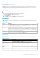
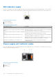
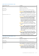
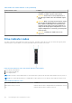

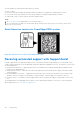
Table Of Contents
- Dell EMC PowerEdge R550 Installation and Service Manual
- Contents
- About this document
- System overview
- Initial system setup and configuration
- Minimum to POST and system management configuration validation
- Installing and removing system components
- Safety instructions
- Before working inside your system
- After working inside your system
- Recommended tools
- Optional front bezel
- System cover
- Drive backplane cover
- Air shroud
- Cooling fans
- Side wall brackets
- Intrusion switch module
- Optional serial COM port
- Drives
- Drive backplane
- Cable routing
- System memory
- Processor and heat sink module
- Expansion cards and expansion card risers
- Optional IDSDM module
- Optional BOSS S2 card
- Front mounting front PERC module
- Optional OCP card
- System battery
- Optional internal USB key
- MicroSD card
- Power supply unit
- Power interposer board
- Cooling fan cage board
- System board
- Trusted Platform Module
- Control panel
- Optional optical drive
- Jumpers and connectors
- System diagnostics and indicator codes
- Getting help
- Documentation resources

Table 38. DC PSU status indicator codes (continued)
Power indicator codes Condition
same power rating. This results in a PSU mismatch
condition, or failure to power on the system.
CAUTION: If two PSUs are used, they must be of
the same type and have the same maximum output
power.
CAUTION: When correcting a PSU mismatch, replace
the PSU with the blinking indicator. Swapping the
PSU to make a matched pair can result in an error
condition and an unexpected system shutdown. To
change from a High Output configuration to a Low
Output configuration or conversely, you must power
off the system.
CAUTION: Combining AC and DC PSUs is not
supported.
Drive indicator codes
The LEDs on the drive carrier indicate the state of each drive. Each drive carrier has two LEDs: an activity LED (green) and a
status LED (bicolor, green/amber). The activity LED blinks whenever the drive is accessed.
Figure 119. Drive indicators on the drive and the mid drive tray backplane
1. Drive activity LED indicator
2. Drive status LED indicator
3. Drive capacity label
NOTE: If the drive is in the Advanced Host Controller Interface (AHCI) mode, the status LED indicator does not power on.
NOTE: Drive status indicator behavior is managed by Storage Spaces Direct. Not all drive status indicators may be used.
Table 39. Drive indicator codes
Drive status indicator code Condition
Blinks green twice per second Indicates that the drive is being identified or preparing for removal.
Off Indicates that the drive is ready for removal.
126 System diagnostics and indicator codes