
Owners Manual
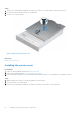
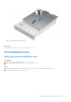
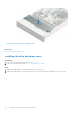
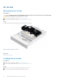
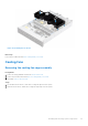
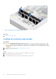
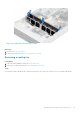
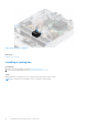
Table Of Contents
- Dell EMC PowerEdge R550 Installation and Service Manual
- Contents
- About this document
- System overview
- Initial system setup and configuration
- Minimum to POST and system management configuration validation
- Installing and removing system components
- Safety instructions
- Before working inside your system
- After working inside your system
- Recommended tools
- Optional front bezel
- System cover
- Drive backplane cover
- Air shroud
- Cooling fans
- Side wall brackets
- Intrusion switch module
- Optional serial COM port
- Drives
- Drive backplane
- Cable routing
- System memory
- Processor and heat sink module
- Expansion cards and expansion card risers
- Optional IDSDM module
- Optional BOSS S2 card
- Front mounting front PERC module
- Optional OCP card
- System battery
- Optional internal USB key
- MicroSD card
- Power supply unit
- Power interposer board
- Cooling fan cage board
- System board
- Trusted Platform Module
- Control panel
- Optional optical drive
- Jumpers and connectors
- System diagnostics and indicator codes
- Getting help
- Documentation resources

Figure 26. Removing the cooling fan cage assembly
Next steps
1. Replace the cooling fan cage.
Installing the cooling fan cage assembly
Prerequisites
1. Follow the safety guidelines listed in the Safety instructions.
CAUTION:
Ensure that the cables inside the system are correctly installed and retained by the cable
retention bracket before installing the cooling fan cage assembly. Incorrectly installed cables may get
damaged.
2. Follow the procedure listed in Before working inside your system.
3. If installed, remove the air shroud.
Steps
1. Align the guide rails on the cooling fan cage with the standoffs on the system.
2. Lower the cooling fan cage into the system.
3. Lower the blue release levers to lock the cooling fan cage into the system.
38
Installing and removing system components