
Owners Manual
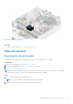
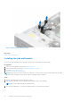
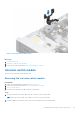
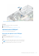
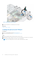

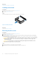
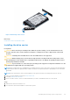
Table Of Contents
- Dell EMC PowerEdge R550 Installation and Service Manual
- Contents
- About this document
- System overview
- Initial system setup and configuration
- Minimum to POST and system management configuration validation
- Installing and removing system components
- Safety instructions
- Before working inside your system
- After working inside your system
- Recommended tools
- Optional front bezel
- System cover
- Drive backplane cover
- Air shroud
- Cooling fans
- Side wall brackets
- Intrusion switch module
- Optional serial COM port
- Drives
- Drive backplane
- Cable routing
- System memory
- Processor and heat sink module
- Expansion cards and expansion card risers
- Optional IDSDM module
- Optional BOSS S2 card
- Front mounting front PERC module
- Optional OCP card
- System battery
- Optional internal USB key
- MicroSD card
- Power supply unit
- Power interposer board
- Cooling fan cage board
- System board
- Trusted Platform Module
- Control panel
- Optional optical drive
- Jumpers and connectors
- System diagnostics and indicator codes
- Getting help
- Documentation resources

Figure 34. Removing the Serial COM port
3. Install the filler bracket if not replacing the serial COM port.
Next steps
Replace the serial COM port.
Installing the optional serial COM port
Prerequisites
1. Follow the safety guidelines listed in the Safety instructions.
2. Follow the procedure listed in the Before working inside your system.
Steps
1. Open the card holder and lift the metal filler bracket from the system.
2. Align and insert the serial COM port into the slot on the system until firmly seated and close the card holder.
3. Connect the serial COM port cable to the connector on the system board.
NOTE: Route the cable properly to prevent the cable from being pinched or crimped.
46 Installing and removing system components