
Owners Manual
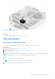
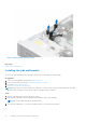
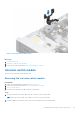
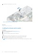
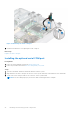

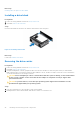
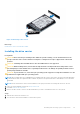
Table Of Contents
- Dell EMC PowerEdge R550 Installation and Service Manual
- Contents
- About this document
- System overview
- Initial system setup and configuration
- Minimum to POST and system management configuration validation
- Installing and removing system components
- Safety instructions
- Before working inside your system
- After working inside your system
- Recommended tools
- Optional front bezel
- System cover
- Drive backplane cover
- Air shroud
- Cooling fans
- Side wall brackets
- Intrusion switch module
- Optional serial COM port
- Drives
- Drive backplane
- Cable routing
- System memory
- Processor and heat sink module
- Expansion cards and expansion card risers
- Optional IDSDM module
- Optional BOSS S2 card
- Front mounting front PERC module
- Optional OCP card
- System battery
- Optional internal USB key
- MicroSD card
- Power supply unit
- Power interposer board
- Cooling fan cage board
- System board
- Trusted Platform Module
- Control panel
- Optional optical drive
- Jumpers and connectors
- System diagnostics and indicator codes
- Getting help
- Documentation resources

Figure 39. Installing a drive carrier
Next steps
If removed, install the front bezel.
Removing the drive from the drive carrier
Prerequisites
1. Follow the safety guidelines listed in the Safety instructions.
2. Remove the drive carrier
Steps
1. Using a Phillips #1 screwdriver, remove the screws from the slide rails on the drive carrier.
NOTE:
If the drive or SSD carrier has Torx screw, use Torx 6 (for 2.5-inch drive) or Torx 8 (for 3.5-inch drive)
screwdriver to remove the drive.
2. Lift the drive out of the drive carrier.
50
Installing and removing system components