
Owners Manual


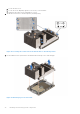
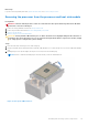


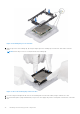

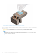
Table Of Contents
- Dell EMC PowerEdge R550 Installation and Service Manual
- Contents
- About this document
- System overview
- Initial system setup and configuration
- Minimum to POST and system management configuration validation
- Installing and removing system components
- Safety instructions
- Before working inside your system
- After working inside your system
- Recommended tools
- Optional front bezel
- System cover
- Drive backplane cover
- Air shroud
- Cooling fans
- Side wall brackets
- Intrusion switch module
- Optional serial COM port
- Drives
- Drive backplane
- Cable routing
- System memory
- Processor and heat sink module
- Expansion cards and expansion card risers
- Optional IDSDM module
- Optional BOSS S2 card
- Front mounting front PERC module
- Optional OCP card
- System battery
- Optional internal USB key
- MicroSD card
- Power supply unit
- Power interposer board
- Cooling fan cage board
- System board
- Trusted Platform Module
- Control panel
- Optional optical drive
- Jumpers and connectors
- System diagnostics and indicator codes
- Getting help
- Documentation resources

● In Optimizer Mode, the DRAM controllers operate independently in the 64-bit mode and provide optimized memory
performance.
Table 23. Memory population rules
Processor Configuration Memory population Memory population
information
Single processor Optimizer (Independent
channel) population order
A{1}, A{2}, A{3}, A{4}, A{5}, A{6},
A{7}, A{8}
1, 2, 3, 4 DIMMs are
allowed.
Dual processor (Start with
processor1. Processor 1
and processor 2 population
should match)
Optimizer (Independent
channel) population order
A{1}, B{1}, A{2}, B{2}, A{3}, B{3},
A{4}, B{4}, A{5}, B{5}, A{6}, B{6},
A{7}, B{7} A{8}, B{8}
1, 2, 3, 4, 5, 6, 7, 8 DIMMs
are supported per system .
NOTE: Optimizer
population order is not
traditional for 8 and 16
DIMMs installations for
dual processor.
● Memory modules of different capacities can be mixed provided other memory population rules are followed.
NOTE: For example, 8 GB and 16 GB memory modules can be mixed.
● Mixing of more than two memory module capacities in a system is not supported.
● Unbalanced or odd memory configuration results in a performance loss and system may not identify the memory modules
being installed, so always populate memory channels identically with equal DIMMs for best performance.
● Supported RDIMM / LRDIMM configurations are 1, 2, 4, 6, 8 DIMMs per processor.
● Populate eight equal memory modules per processor (one DIMM per channel) at a time to maximize performance.
NOTE:
Equal memory modules refer to DIMMs with identical electrical specification and capacity that may be from
different vendors.
Removing a memory module
Prerequisites
1. Follow the safety guidelines listed in the Safety instructions.
2. Follow the procedure listed in the Before working inside your system.
3. Remove the air shroud.
WARNING:
The memory modules are hot to touch for some time after the system has been powered off. Allow
the memory modules to cool before handling them.
Steps
1. Locate the appropriate memory module socket.
2. To release the memory module from the socket, simultaneously press the ejectors on both ends of the memory module
socket to fully open.
CAUTION:
Handle each memory module only by the card edges, ensuring not to touch the middle of the
memory module or metallic contacts.
3. Lift the memory module away from the system.
Installing and removing system components
61