
Owners Manual
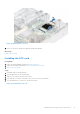
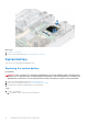


Table Of Contents
- Dell EMC PowerEdge R550 Installation and Service Manual
- Contents
- About this document
- System overview
- Initial system setup and configuration
- Minimum to POST and system management configuration validation
- Installing and removing system components
- Safety instructions
- Before working inside your system
- After working inside your system
- Recommended tools
- Optional front bezel
- System cover
- Drive backplane cover
- Air shroud
- Cooling fans
- Side wall brackets
- Intrusion switch module
- Optional serial COM port
- Drives
- Drive backplane
- Cable routing
- System memory
- Processor and heat sink module
- Expansion cards and expansion card risers
- Optional IDSDM module
- Optional BOSS S2 card
- Front mounting front PERC module
- Optional OCP card
- System battery
- Optional internal USB key
- MicroSD card
- Power supply unit
- Power interposer board
- Cooling fan cage board
- System board
- Trusted Platform Module
- Control panel
- Optional optical drive
- Jumpers and connectors
- System diagnostics and indicator codes
- Getting help
- Documentation resources

a. Enter the System Setup, while booting, by pressing F2.
b. Enter the correct time and date in the System Setup Time and Date fields.
c. Exit the System Setup.
d. To test the newly installed battery, remove the system from the enclosure for at least an hour.
e. Reinstall the system into the enclosure after an hour.
f. Enter the System Setup and if the time and date are still incorrect, see Getting help section.
Optional internal USB key
Removing the internal USB card
Prerequisites
CAUTION: To avoid interference with other components in the server, the maximum permissible dimensions of
the USB memory key are 15.9 mm width x 57.15 mm length x 7.9 mm height.
1. Follow the safety guidelines listed in the Safety instructions.
2. Follow the procedure listed in the Before working inside your system.
Steps
1. Holding the blue tag, lift the internal USB card to disconnect from the connector on the system board.
2. Remove the USB memory key from the internal USB card.
Figure 92. Removing the internal USB card
Next steps
Replace the internal USB card.
Installing the internal USB card
Prerequisites
1. Follow the safety guidelines listed in the Safety instructions.
94
Installing and removing system components