Dell Technologies PowerEdge RAID Controller 11 User’s Guide PERC H755 adapter, H755 front SAS, H755N front NVMe, and PERC H755 MX adapter Regulatory Model: UCPA-1101, UCPF-1100, UCPF-1110, and UCPN-1100 May 2021 Rev.
Notes, cautions, and warnings NOTE: A NOTE indicates important information that helps you make better use of your product. CAUTION: A CAUTION indicates either potential damage to hardware or loss of data and tells you how to avoid the problem. WARNING: A WARNING indicates a potential for property damage, personal injury, or death. © 2020-2021 Dell Inc. or its subsidiaries. All rights reserved. Dell, EMC, and other trademarks are trademarks of Dell Inc. or its subsidiaries.
Contents Chapter 1: Dell Technologies PowerEdge RAID Controller 11.......................................................... 8 Features of PERC H755 adapter..................................................................................................................................... 9 Features of PERC H755 front SAS................................................................................................................................. 9 Features of PERC H755N front NVMe........................
Battery Transparent Learn Cycle.............................................................................................................................27 Operating system device enumeration................................................................................................................... 27 Chapter 4: Install and remove a PERC 11 card.............................................................................. 29 Safety instructions......................................................
Disable security.............................................................................................................................................................51 Change security settings........................................................................................................................................... 52 Restore factory default settings..............................................................................................................................
Firmware fault state error message.............................................................................................................................. 71 Foreign configuration found error message.................................................................................................................71 Foreign configuration not found in HII error message.............................................................................................. 71 Degraded state of virtual disks..........
Chapter 11: Getting help.............................................................................................................. 84 Recycling or End-of-Life service information.............................................................................................................84 Contacting Dell..................................................................................................................................................................
1 Dell Technologies PowerEdge RAID Controller 11 Dell Technologies PowerEdge RAID Controller 11, or PERC 11 is a series of RAID disk array controllers made by Dell for its PowerEdge servers.
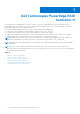
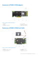
Features of PERC H755 adapter Figure 1. Features of PERC H755 adapter 1. Heatsink 3. Battery 5. Backplane connector B 2. PCIe connector 4. Backplane connector A 6. Battery cable connector Features of PERC H755 front SAS Figure 2. Features of PERC H755 front SAS 1. Battery 3. Power card edge connector 5. Backplane connector A 2. PCIe input connector 4. Heatsink 6.
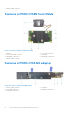
7. Battery cable connector Features of PERC H755N front NVMe Figure 3. Features of PERC H755N front NVMe 1. 3. 5. 7. Battery Power card edge connector Backplane connector A Battery cable connector 2. PCIe cable connector 4. Heatsink 6. Backplane connector B Features of PERC H755 MX adapter Figure 4. Features of PERC H755 MX adapter 1. Battery cable connector 3. PCIe cable connector 5. Backplane connector B 10 Dell Technologies PowerEdge RAID Controller 11 2. Heatsink 4.
Technical specifications of PERC 11 cards The table below lists and describes the different PERC 11 cards series and their specifications: Table 1.
Table 1.
2 Applications and User Interfaces supported by PERC 11 PERC 11 card Management applications include the Comprehensive Embedded Management (CEM), Dell OpenManage Storage Management, The Human Interface Infrastructure (HII) configuration utility, and The PERC Command Line Interface (CLI). They enable you to manage and configure the RAID system, create and manage multiple disk groups, control and monitor multiple RAID systems, and provide online maintenance.
The PERC Command Line Interface The PERC Command Line Interface (CLI) is a storage management application. This utility allows you to set up, configure, and manage your Dell PowerEdge RAID Controller (PERC) by using the Command Line Interface (CLI). NOTE: For more information, see Dell EMC PowerEdge RAID Controller CLI Reference Guide at www.dell.com/ storagecontrollermanuals.
3 Features of PowerEdge RAID Controller 11 Topics: • • • • Controller features Virtual disk features Hard drive features Fault tolerance Controller features This section lists the following controller features supported on Dell Technologies PowerEdge RAID Controller 11 cards in detail: ● Non-Volatile Memory Express ● Opal Security Management ● Hardware Root of Trust ● 1 MB I/O ● Auto Configure RAID 0 ● Disk roaming ● FastPath ● Non–RAID disks ● Physical disk power management ● Profile Management ● Secure
Drive repair for NVMe initialization failure If an NVME drive fails to initialize, the drive that is connected to PERC can be corrected in HII. The NVME initialization errors in the drives are listed as correctable and non-correctable errors in HII. Repair drives with correctable NVMe initialization errors Repair the drives with correctable NVMe initialization errors in HII to enable the drives to work properly. About this task Repairs can lead to permanent data loss in drives.
Table 2.
Physical disk power management Physical disk power management is a power-saving feature of PERC 11 series cards. The feature allows disks to be spun down based on disk configuration and I/O activity. The feature is supported on all rotating SAS and SATA disks, and includes unconfigured and hot-spare disks. The physical disk power management feature is disabled by default.
Table 4. Write cache policies Feature Description Write-back The controller sends a data transfer completion signal to the host when the controller cache has received all the data in a transaction. The controller then writes the cached data to the storage device in the background. NOTE: The default cache setting for virtual disks is Write-back caching. Write-back caching is also supported for single drive RAID 0 virtual disks.
● Supports migration of virtual disks from PERC H345, H740P, H745, H745P MX, and H840 to the PERC 11 series except for H345. ● Supports migration of volumes created within the PERC 11 series. ● Does not support migration from the PERC 11 series to PERC H345, H740P, H745, H745P MX, and H840. ● Does not support migration from PERC H330, H730, and H830 to the PERC 11 series. NOTE: The source controller must be offline prior to performing the disk migration.
NOTE: Reconfiguring virtual disks typically impacts disk performance until the reconfiguration operation is complete. Online Capacity Expansion (OCE) can be done in two ways: 1. If there is a single virtual disk in a disk group and free space is available, the capacity of a virtual disk can be expanded within that free space. If multiple virtual disks exist within a common disk group, the capacities of those virtual disks cannot be expanded.
See the following table for a list of RLM or OCE options: The source RAID level column indicates the virtual disk RAID level before the RLM or OCE operation and the target RAID level column indicates the RAID level after the RLM or OCE operation. Table 6. RAID level migration Source RAID Level Target RAID Level Number of Physical Disks (Beginning) Number of Physical Disks (End) Capacity Expansion Possible Description RAID 0 RAID 0 1 or more 2 or more Yes Increases capacity by adding disks.
Background operations Background initialization Background initialization (BGI) is an automated process that writes parity or mirror data on newly created virtual disks. BGI does not run on RAID 0 virtual disks. You can control the BGI rate in the Dell OpenManage storage management application. Any change to the BGI rate does not take effect until the next BGI is executed. NOTE: ● You cannot disable BGI permanently. If you cancel BGI, it automatically restarts within five minutes.
Instant secure erase Instant Secure Erase (ISE) drives use the same encryption technology as SED drives but do not allow the encryption key to be secured. The encryption technology allows the drive to be re-purposed and securely erased using the cryptographic erase function. NOTE: ISE drives do not provide protection against theft. 4 KB sector disk drives PERC 11 controllers support 4 KB sector disk drives, which enables you to efficiently use the storage space.
Patrol Read The Patrol read feature is designed as a preventative measure to ensure physical disk health and data integrity. Patrol read scans and resolves potential problems on configured physical disks. The Dell storage management applications can be used to start patrol read and change its behavior. The following is an overview of patrol read behavior: ● Patrol read runs on all disks on the controller that are configured as part of a virtual disk, including hot spares.
Table 7. Drive state/operation (continued) Drive state/operation Unconfigured slot Slot configured in VD ● Original drive data lost Insert locked drive into the system (non-unlockable) Foreign locked Foreign locked Physical disk hot swapping Hot swapping is the manual replacement of a disk while the PERC 11 series cards are online and performing their normal functions.
Cache preservation with non–volatile cache The non–volatile cache (NVC) allows controller cache data to be stored indefinitely. If the controller has data in the cache memory during a power outage or improper system shutdown, a small amount of power from the battery is used to transfer the cache data to non-volatile flash storage where it remains until power is restored and the system is booted.
resulting in the operating system enumeration changing after reboot. It is recommended to reboot the system for the final device enumeration after creating any virtual disks or non-RAID disks.
4 Install and remove a PERC 11 card Topics: • • • • • • • • • • • Safety instructions Before working inside your system After working inside your system Remove the PERC H755 adapter Install the PERC H755 adapter Remove the PERC H755 front SAS card Install the PERC H755 front SAS card Remove the PERC H755N front NVMe card Install the PERC H755N front NVMe card Remove the PERC H755 MX adapter Install the PERC H755 MX adapter Safety instructions NOTE: To avoid injury, do not lift the system on your own.
Before working inside your system Steps 1. Power off the system and all attached peripherals. 2. Disconnect the system from the electrical outlet, and disconnect the peripherals. 3. If applicable, remove the system from the rack. For more information, see the Rail Installation Guide relevant to your rail solutions at www.dell.com/poweredgemanuals. 4. Remove the system cover. After working inside your system Steps 1. Replace the system cover. 2. If applicable, install the system into the rack.
Figure 5. Remove the PERC H755 adapter Install the PERC H755 adapter Prerequisites CAUTION: Many repairs may only be done by a certified service technician. You should only perform troubleshooting and simple repairs as authorized in your product documentation, or as directed by the online or telephone service and support team. Damage due to servicing that is not authorized by Dell is not covered by your warranty. Read and follow the safety instructions that are shipped with your product.
Figure 6. Install the PERC H755 adapter Remove the PERC H755 front SAS card Prerequisites CAUTION: Many repairs may only be done by a certified service technician. You should only perform troubleshooting and simple repairs as authorized in your product documentation, or as directed by the online or telephone service and support team. Damage due to servicing that is not authorized by Dell is not covered by your warranty. Read and follow the safety instructions that are shipped with your product.
7. Insert the replacement controller into the carrier and secure it with the appropriate screws. 8. Take the replacement storage controller and reconnect the cables before reconnecting it to the backplane. If you are removing a PERC H755 front SAS controller in the upside down orientation, reattach the PERC controller to the backplane first before reinstalling the backplane into the system. For more information on installing the card, see Install PERC H755 front SAS card. 9. Close the system. 10.
NOTE: Perform a graceful shutdown of the sled to ensure that data in the cache is moved to the disk before the controller is removed. 2. Open the system. 3. Connect the PERC card to the carrier and ensure that the screws are properly fastened in place. CAUTION: To prevent damage to the card, hold the card by its edges only. 4. Align the carrier with the guide pins until the controller is securely seated. 5. Slide the card into the connector until it is fully seated in the connector.
telephone service and support team. Damage due to servicing that is not authorized by Dell is not covered by your warranty. Read and follow the safety instructions that are shipped with your product. NOTE: It is recommended that you always use a static mat and static strap while working on components in the interior of the system. Steps 1. Turn off the system, including any attached peripherals, and disconnect the system from the electrical outlet and peripherals.
Figure 9. Remove the PERC H755N front NVMe card Install the PERC H755N front NVMe card Prerequisites CAUTION: Many repairs may only be done by a certified service technician. You should only perform troubleshooting and simple repairs as authorized in your product documentation, or as directed by the online or telephone service and support team. Damage due to servicing that is not authorized by Dell is not covered by your warranty. Read and follow the safety instructions that are shipped with your product.
5. Slide the card until it is fully seated in the connector. Tighten the screws on the carrier that connect to the chassis to secure the carrier. 6. Connect the cable connectors to the card. NOTE: Ensure that you connect the cable according to the connector labels on the cable. The cable does not function properly if reversed. 7. Close the system. 8. Reconnect the system to its electrical outlet and turn on the system and any attached peripherals. Figure 10.
Steps 1. Turn off the sled, including any attached peripherals, and remove the sled from the MX chassis. NOTE: Perform a graceful shutdown of the system to ensure that data in the cache is moved to the disk before the controller is removed. 2. Open the sled. 3. Locate the PERC card on the system board. CAUTION: To prevent damage to the card, hold the card by its edges only. 4. Using the blue tab, rotate the lever of the controller. 5.
telephone service and support team. Damage due to servicing that is not authorized by Dell is not covered by your warranty. Read and follow the safety instructions that are shipped with your product. NOTE: It is recommended that you always use a static mat and static strap while working on components in the interior of the system. Steps 1. Turn off the sled and any attached peripherals, and remove the sled from the MX chassis. 2. Open the sled. 3. Connect the backplane data cable connector to the card.
5 Driver support for PERC 11 The PERC 11 series require software drivers to operate with the supported operating systems. This chapter contains the procedures for installing the drivers for the PERC 11 cards. NOTE: The driver for PERC 11 for VMware ESXi is packaged within the VMware ESXi ISO image downloaded from Dell. For more information, see the VMware documentation at www.dell.com/virtualizationsolutions. It is not recommended to have drivers from controllers prior to PERC 11 on the same system.
Steps 1. Insert the Dell Systems Service and Diagnostics Tools media in your system. The Welcome to Dell Service and Diagnostic Utilities screen is displayed. 2. Select your system model and operating system. 3. Click Continue. 4. From the list of drivers displayed, select the driver you require. 5. Select the self-extracting ZIP file and click Run. 6. Copy the driver to a CD, DVD, or USB drive. 7. Repeat steps 1 to 6 for all the drivers you require.
5. On the Locate device driver screen, select Search for a suitable driver for my device and click Next. 6. Browse and select the drivers from the Locate Driver Files screen. 7. Click Next. The wizard detects and installs the appropriate device drivers for the new RAID controller. 8. Click Finish to complete the installation. 9. Reboot the system when prompted.
Install or update a RPM driver package using the KMOD support Prerequisites NOTE: This procedure is applicable for Red Hat Enterprise Linux 7.x and higher. About this task Perform the following steps to install the RPM package with KMOD support: Steps 1. Uncompress the gzipped tarball driver release package. 2. Install the driver package using the command: rpm –ihv kmodmegaraid_ sas-.rpm. NOTE: Use rpm -Uvh when upgrading an existing package. 3.
Loading the driver while installing an operating system Steps 1. Perform the following operation to install the driver media: a. Download the PERC linux driver ISO, or install the LC driver pack. b. Mount the ISO to the Server, burn the ISO to CD/DVD, or copy the ISO file to USB. The USB has to match with the ISO. c. For LC driver pack, boot the life-cycle controller and go through the operating system deployment wizard. 2. Boot to the installer. 3. In the Installation screen, press E. 4.
6 Firmware This section provides information about downloading and installing the firmware using Dell Update Package (DUP). Topics: • Install the PERC 11 firmware using Dell Update Package (DUP) Install the PERC 11 firmware using Dell Update Package (DUP) Steps 1. Navigate to www.dell.com/support/home. 2. Locate your controller. 3. Download the DUP. a. For Window/iDRAC update, download Windows executable file. b. For Linux update, download .bin file.
7 Manage PERC 11 controllers using HII configuration utility The Human Interface Infrastructure (HII) configuration utility is a storage management application integrated into the System BIOS . It is used to configure and manage the controller(s), virtual disks, and physical disks. This utility is independent of the operating system.
Navigate to Dell PERC 11 configuration utility Steps 1. Enter the UEFI configuration Utility. See Enter the PERC 11 HII configuration utility. The Device Settings screen displays a list of NIC ports and the RAID controllers. 2. To enter PERC 11 configuration utility, click the appropriate PERC controllers. The Dashboard view screen is displayed. View the HII Configuration utility dashboard The first screen that is displayed when you access the HII Configuration Utility is the Dashboard View screen.
Configuration management Auto Configure RAID 0 Steps 1. Enter the Dell PERC 11 Configuration Utility. See Navigate to Dell PERC 11 configuration utility. 2. Click Main Menu > Configuration Management > Auto Configure RAID 0. 3. Select Confirm and click Yes to continue. A RAID 0 Virtual disk is created on all physical disks that are in Ready state. Create virtual disks Steps 1. Enter the Dell PERC 11 Configuration Utility. See, Navigate to Dell PERC 11 configuration utility. 2.
2. In the Configure Virtual Disk Parameters section, you can set the following virtual disk parameters: Table 9. Configure virtual disk parameters Virtual disk parameters Description Virtual Disk Name Allows you to enter the name for the virtual disk NOTE: Allowed characters are A-Z, a-z, 0-9, underscore (_), and hyphen (-) only.
6. Select Confirm and click Yes to continue. The virtual disk is created with the parameters of the profile selected. View disk group properties Steps 1. Enter the Dell PERC 11 Configuration Utility. See Navigate to Dell PERC 11 configuration utility. 2. Click Main Menu > Configuration Management > View Disk Group Properties. The list of disk group properties are displayed: Properties Descriptions Capacity Allocation Displays all the virtual disks associated with the specific disk group.
2. Click Main Menu > Controller Management > Advanced Controller Management. 3. Click Clear Controller Events. A screen is displayed asking if you are sure you want to clear the controller events. 4. Select Confirm and click Yes to continue. Save controller events Steps 1. Enter the Dell PERC 11 Configuration Utility. See Navigate to Dell PERC 11 configuration utility. 2. Click Main Menu > Controller Management > Advanced Controller Management. 3. Click Save Controller Events.
Change security settings Steps 1. Enter the Dell PERC 11 Configuration Utility. See Navigate to Dell PERC 11 configuration utility. 2. Click Main Menu > Controller Management > Advanced Controller Management. 3. Click Change Security Settings, select Change Current Security Settings. 4. Click Ok. 5. If you want to use the passphrase generated by the controller, click Suggest Passphrase and Confirm the passphrase by re-entering. The operation is successful. 6. Click Save Security Settings. 7.
Advanced controller properties Set the patrol read mode Steps 1. Enter the Dell PERC 11 Configuration Utility. See Navigate to Dell PERC 11 configuration utility. 2. Click Main Menu > Controller Management > Advanced Controller Properties. 3. Click Patrol Read. The following options are displayed: ● Start—Starts patrol read for the selected controller. ● Suspend—Suspends the ongoing patrol read operation on the controller. ● Resume—Resumes the suspended patrol read operation.
The following options are displayed: ● Background Initialization (BGI) Rate ● Consistency Check Rate ● Rebuild Rate ● Reconstruction Rate 4. You can make the necessary changes and then click Apply Changes. The task rates operation is completely successfully. Properties of Enterprise Key Management (EKM) Steps 1. Enter the Dell PERC 11 Configuration Utility. See Navigate to Dell PERC 11 configuration utility. 2. Click Main Menu > Controller Management > Advanced Controller Properties. 3.
Table 10. Boot mode options Option Description Stop on errors The system stops during boot for errors which require attention from the user to rectify the issue. Pause on errors System pauses during boot to show errors but continue boot after it times out. Only critical events with an infinite timeout halt boot and require the user’s attention to correct the issue. NOTE: In UEFI BIOS mode, errors with timeouts do not appear during boot. It is designed to arise only in legacy BIOS mode.
If no boot device is selected, the first virtual disk will be set as the boot device on the next reboot. A Non–RAID disk is auto-selected as the boot device, if the controller does not have any virtual disks present. NOTE: Select Boot Device is only applicable in legacy BIOS mode. NOTE: 4 K sector drives boot support is only available in UEFI mode and managed by the boot loader. 4. Click Apply Changes. Boot support is enabled for the selected controller.
4. Click View Associated Physical Disks. All the physical disks that are associated with the virtual disk are displayed. 5. From the Associated Physical Disks section, select the physical disk. 6. Click View Physical Disk Properties to view the physical disk properties. View physical disks associated with a virtual disk Steps 1. Enter the Dell PERC 11 Configuration Utility. See Navigate to Dell PERC 11 configuration utility. 2. Click Main Menu > Virtual Disk Management.
Configure Virtual Disks When configuring the virtual disks, you should consider the workload intended; RAID 1: for simple boot disk; RAID 5 or 6: for file or web servers (sequential reads/writes of files); RAID 10: for transactional database (small random reads and writes). Virtual disks configured on hard drives should use the controller default cache setting of Write Back and Read Ahead. Virtual disks configured on SSDs can use the same controller defaults settings as hard drives.
A screen is displayed asking if you are sure you want to perform the operation. 6. Select the Confirm option. 7. Click Yes. The consistency check operation is completed successfully. Physical disk management View physical disk properties Steps 1. Enter the Dell PERC 11 Configuration Utility. See Navigate to Dell PERC 11 configuration utility. 2. Click Main Menu > Physical Disk Management. All the physical disks associated with the RAID controller are displayed. 3.
Table 15. Advanced physical disk properties (continued) Option Description NOTE: Disk cache for SATA Gen3 drives is disabled by default.
A screen is displayed asking if you are sure you want to perform the operation. 6. Select the Confirm option. 7. Click Yes. The physical disk erase operation is completed successfully. Assigning a global hot spare Prerequisites To assign a global hot spare from the HII Configuration Utility, perform the following steps: Steps 1. Enter the Dell PERC 11 Configuration Utility. See Navigate to Dell PERC 11 configuration utility. 2. Click Main Menu > Physical Disk Management.
A screen appears asking if you are sure you want to perform the operation. 6. Select the Confirm option. 7. Click Yes. The operation is successful. Convert to Non–RAID disk Prerequisites To convert a physical disk to non–RAID disk from the HII Configuration Utility, perform the following steps: Steps 1. Enter the Dell PERC 11 Configuration Utility. See Navigate to Dell PERC 11 configuration utility. 2. Click Main Menu > Physical Disk Management. The list of physical disks appears. 3.
Table 17. Advanced battery properties (continued) Field Description Current Displays power consumption of the battery in milliamps (mA). Full capacity Displays the maximum charge capacity of the battery. Remaining capacity Displays the current charge capacity of the battery. Expected margin of error Displays expected margin of error. Completed discharge cycles Displays the completed discharge cycles. Learn mode Displays the condition of the battery.
8 Security key and RAID management Topics: • • • • • • • • • • • Security key implementation Local Key Management Create a security key Change Security Settings Disable security key Create a secured virtual disk Secure a non-RAID disk Secure a pre-existing virtual disk Import a secured non-RAID disk Import a secured virtual disk Dell Technologies OpenManage Secure Enterprise Key Manager Security key implementation The PERC 11 series of cards support self-encrypting disk (SED) for protection of data agains
NOTE: The Security Key Identifier is a user supplied clear text label used to associate the correct security key with the controller. 6. If you want to use the passphrase generated by the controller, click Suggest Passphrase. Assigns a passphrase suggested by the controller automatically. 7. In the Passphrase field, enter the passphrase. NOTE: Passphrase is case-sensitive. You must enter minimum 8 or maximum 32 characters.
Create a secured virtual disk About this task To create a secured virtual disk, the controller must have a security key established first. See Create a security key. NOTE: Combining SAS and SATA hard drives within a virtual disk is not supported. Also, combining hard drives and olid-state drives (SSDs) within a virtual disk is not supported. Mixing of NVMe drives is not supported. After the security key is established, perform the following steps: Steps 1. Enter the Dell PERC 11 Configuration Utility.
2. Click Main Menu > Configuration Management > Manage Foreign Configurations. 3. Click Enter Passphrase for Locked Disks. A screen is displayed asking if you are sure you want to perform the operation. 4. Enter Passphrase if importing non-RAID disk with a different passphrase. 5. Select the Confirm option. 6. Click Yes. NOTE: If Auto-Configure for non-RAID Disks is enabled, the disk becomes a non-RAID disk. Else, it is unconfigured.
Manage enterprise key manager mode Enterprise key manager features are managed by iDRAC. For instructions on enabling enterprise key manager mode, see www.dell.com/idracmanuals. NOTE: If preserved cache is present, the controller will not allow OpenManage Secure Enterprise Key Manager mode to be enabled. NOTE: Transitioning a controller from LKM mode to enterprise key manager mode without disabling security or the reverse is not supported.
9 Troubleshooting To get help with your Dell Technologies PowerEdge RAID Controller 11 series, you can contact your Dell Technical Service representative or see https://www.dell.com/support.
Probable Cause: The message indicates that some configured disks were removed. If the disks were not removed, they are no longer accessible. The cables from the PERC controller to the backplane might be improperly connected. Corrective Action: Check the cable connections and fix issues if any. Restart the system. If there are no cable problems, press any key or to continue. Dirty cache data error message Error Message: The following virtual disks are missing: (x).
Windows operating system installation errors Ensure that you perform the following step before installing Windows on 4 KB sector drives: 1. Read and understand the updates to the version of Windows that you have installed. You can find this information in the Microsoft help. For more information, see Microsoft support policy for 4 K sector hard drives in Windows. Firmware fault state error message Error Message: Firmware is in Fault State. Corrective Action: Contact Global Technical Support.
Multi-bit errors are more serious as they result in corrupted data and data loss. The following are the actions that occur in the case of multi-bit errors: ● If a multi-bit error occurs while accessing data in the cache when the controller is started with dirty cache, the controller discards the cache contents. The controller generates a warning message to the system console to indicate that the cache was discarded and generates an event.
Failure of Cryptographic Erase task on secured physical disks Cryptographic Erase is the process of securely erasing all data permanently on an encryption-capable physical disk and resetting the security attributes. It is used in a couple of scenarios such as deleting a foreign configuration in the event of a forgotten or lost passphrase or unlocking a disk that had been previously locked.
Multiple disks are inaccessible Issue: Multiple disks are simultaneously inaccessible. Probable Cause: Multiple physical disk errors in a single array typically indicate a failure in cabling or connection and could involve the loss of data. Corrective Action: You can recover the virtual disk after multiple physical disks become simultaneously inaccessible. Perform the following steps to recover the virtual disk: CAUTION: Follow the safety precautions to prevent electrostatic discharge. 1. 2. 3. 4. 5.
Redundant virtual disk fails during reconstruction Issue: Multiple disks fails during a reconstruction process on a redundant virtual disk that has a hot spare. Probable Cause: Multiple physical disks in the virtual disk is failed or the cables are disconnected. Corrective Action: No action is required. The physical disk to which a reconstruction operation is targeted reverts to Ready state, and the virtual disk goes to Failed state.
2. Replace the affected physical disk with a new physical disk of equal or higher capacity. 3. Restore from the backup. Smart error detected on a physical disk in a non–redundant virtual disk Issue: A SMART error is detected on a physical disk in a non–redundant virtual disk. Corrective Action: Perform the following steps: 1. Back up your data. 2. Use Replace Member to replace the disk manually. NOTE: For more information about the Replace Member feature, see Configure hot spare drives. 3.
Probable Cause: Physical disk failure or physical disk is removed or disconnected. Corrective Action: It is recommended that you replace or check the target drive, and restart the Replace Member operation or perform the operation on a different target drive.
Drive indicator codes The LEDs on the drive carrier indicates the state of each drive. Each drive carrier has two LEDs: an activity LED (green) and a status LED (bicolor, green/amber). The activity LED blinks whenever the drive is accessed. Figure 13. Drive indicators 1. Drive activity LED indicator 2. Drive status LED indicator 3. Drive capacity label If the drive is in the Advanced Host Controller Interface (AHCI) mode, the status LED indicator does not power on.
Corrective Action: 1. Check if the cables are connected properly, or replace missing hard drives, if any and then restart the system. 2. Press any key to load the driver health manager to display the configurations. The Driver Health Manager displays the driver(s), which requires configuration. 3. Alternately, if the UEFI driver requires configuration, press any key to load the Configuration Utility.
10 Appendix RAID description RAID is a group of independent physical disks that provides high performance by increasing the number of disks used for saving and accessing data. CAUTION: In the event of a physical disk failure, a RAID 0 virtual disk fails, resulting in data loss. A RAID disk subsystem offers the following benefits: ● Improved I/O performance and data availability. ● Improved data throughput because several disks are accessed simultaneously.
NOTE: The maximum number of virtual disks is currently limited to 192, because of the supported enclosure configuration. RAID 10 configuration In PERC 10 and PERC 11 controllers, RAID 10 can be configured without spanning up to 32 drives. Any RAID 10 volume that has more than 32 drives require spanning. Each span can contain up to 32 drives. Drives must be distributed evenly across all the spans with each span containing an even number of drives.
Table 20. RAID 10 configurations (continued) Disk or span count RAID 10 capable Disk or span count RAID 10 capable Disk or span count RAID 10 capable Disk or span count RAID 10 capable 60 (2) Yes 120 (4) Yes 180 (6) Yes 240 (8) Yes 62 No 122 No 182 (7) Yes - - RAID terminology Disk striping Disk striping allows you to write data across multiple physical disks instead of just one physical disk.
Spanned RAID levels Spanning is a term used to describe the way in which RAID levels 10, 50, and 60 are constructed from multiple sets of basic, or simple RAID levels. For example, a RAID 10 has multiple sets of RAID 1 arrays where each RAID 1 set is considered a span. Data is then striped (RAID 0) across the RAID 1 spans to create a RAID 10 virtual disk. Similarly, RAID 50 and RAID 60 combine multiple sets of RAID 5 or RAID 6 respectively with striping.
11 Getting help Topics: • • • • Recycling or End-of-Life service information Contacting Dell Locating the Express Service Code and Service Tag Receiving automated support with SupportAssist Recycling or End-of-Life service information Take back and recycling services are offered for this product in certain countries. If you want to dispose of system components, visit www.dell.com/recyclingworldwide and select the relevant country.
Figure 18. Locating the Express Service Code and Service tag 1. Information tag (front view) 3. OpenManage Mobile (OMM) label 5. Service Tag, Express Service Code, QRL label 2. Information tag (back view) 4. iDRAC MAC address and iDRAC secure password label The Mini Enterprise Service Tag (MEST) label is located on the rear of the system that includes Service Tag (ST), Express Service Code (Exp Svc Code), and Manufacture Date (Mfg. Date).
12 Documentation resources This section provides information about the documentation resources for your system. To view the document that is listed in the documentation resources table: ● From the Dell EMC support site: 1. Click the documentation link that is provided in the Location column in the table. 2. Click the required product or product version. NOTE: To locate the product name and model, see the front of your system. 3. On the Product Support page, click Manuals & documents.
Table 21. Additional documentation resources for your system (continued) Task Managing your system Document Location For information about installing the operating system, see the operating system documentation. www.dell.com/operatingsystemmanuals For information about updating drivers and firmware, see the Methods to download firmware and drivers section in this document. www.dell.