
Owners Manual
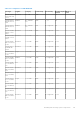
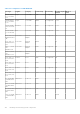

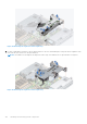
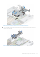

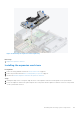
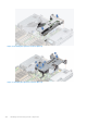
Table Of Contents
- Dell EMC PowerEdge R6525 Installation and Service Manual
- Contents
- About this document
- System overview
- Initial system setup and configuration
- Installing and removing system components
- Safety instructions
- Before working inside your system
- After working inside your system
- Recommended tools
- Cable routing
- RIO card
- Tube clip
- Optional front bezel
- System cover
- Drive backplane cover
- Control panel
- VGA module
- Air shroud
- Cooling fan
- Drives
- Drive backplane
- Rear drive module
- Front PERC module
- System memory
- Processor and heat sink
- Expansion cards and expansion card risers
- Optional serial COM port
- Optional IDSDM module
- MicroSD card
- M.2 SSD module
- BOSS S2 card (optional)
- System battery
- Optional internal USB card
- Intrusion switch module
- Optional OCP card
- Power supply unit
- Trusted Platform Module
- System board
- LOM card and rear I/O board
- Upgrade Kits
- Jumpers and connectors
- System diagnostics and indicator codes
- Getting help
- Documentation resources

Table 28. Configuration 7: R1D+R2B+R3A
Card type Supplier Category Card Priority Slot Priority Bracket Height
Allowed
Max # of
Cards
KIT,CRD,NVME,
6.4,HHHL,PM17
25B
SAMSUNG PCIE SSD 11900 3 LP/FH 1
KIT,CRD,NVME,
1.6,HHHL,PM17
35
SAMSUNG PCIE SSD 12000 3 LP/FH 1
KIT,CRD,NVME,
1.6,HHHL,PM17
35,O
SAMSUNG PCIE SSD 12100 3 LP/FH 1
KIT,CRD,NVME,
3.2,HHHL,PM17
35
SAMSUNG PCIE SSD 12200 3 LP/FH 1
KIT,CRD,NVME,
3.2,HHHL,PM17
35,O
SAMSUNG PCIE SSD 12300 3 LP/FH 1
KIT,CRD,NVME,
6.4,HHHL,PM17
35
SAMSUNG PCIE SSD 12400 3 LP/FH 1
KIT,CRD,NVME,
6.4,HHHL,PM17
35,O
SAMSUNG PCIE SSD 12500 3 LP/FH 1
KIT,CRD,NVME,
750GB,HHHL,P
4800X
INTEL PCIE SSD 12600 3 LP/FH 1
KIT,CRD,NVME,
375GB,HHHL,P
4800X
INTEL PCIE SSD 12700 3 LP/FH 1
KIT, CRD, CTL,
HBA355E
FOXCONN External
Adapter
13500 3 LP/FH 1
CRD,CTL,PCIE,
375GB,HHHL,P
4800X
INTEL PCIE SSD 12800 3 LP/FH 1
Removing the expansion card risers
Prerequisites
1. Follow the safety guidelines listed in the Safety instructions on page 26.
2. Follow the procedure listed in the Before working inside your system on page 27.
3. Disconnect any cables that are connected to the expansion card.
Steps
1. For Riser 1, press the blue tab and holding the edges lift the expansion card riser from the riser connector on the system
board.
Installing and removing system components
103