
Owners Manual
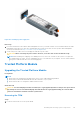
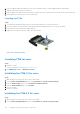

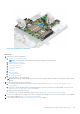

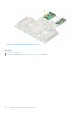
Table Of Contents
- Dell EMC PowerEdge R6525 Installation and Service Manual
- Contents
- About this document
- System overview
- Initial system setup and configuration
- Installing and removing system components
- Safety instructions
- Before working inside your system
- After working inside your system
- Recommended tools
- Cable routing
- RIO card
- Tube clip
- Optional front bezel
- System cover
- Drive backplane cover
- Control panel
- VGA module
- Air shroud
- Cooling fan
- Drives
- Drive backplane
- Rear drive module
- Front PERC module
- System memory
- Processor and heat sink
- Expansion cards and expansion card risers
- Optional serial COM port
- Optional IDSDM module
- MicroSD card
- M.2 SSD module
- BOSS S2 card (optional)
- System battery
- Optional internal USB card
- Intrusion switch module
- Optional OCP card
- Power supply unit
- Trusted Platform Module
- System board
- LOM card and rear I/O board
- Upgrade Kits
- Jumpers and connectors
- System diagnostics and indicator codes
- Getting help
- Documentation resources

3. From the TPM Security option, select On.
4. Save the settings.
5. Restart your system.
System board
Removing the system board
Prerequisites
CAUTION: If you are using the Trusted Platform Module (TPM) with an encryption key, you may be prompted
to create a recovery key during program or System Setup. Be sure to create and safely store this recovery key.
If you replace this system board, you must supply the recovery key when you restart your system or program
before you can access the encrypted data on your drives.
1. Follow the safety guidelines listed in the Safety instructions on page 26.
2. Follow the procedure listed in the Before working inside your system on page 27.
3. Remove the following components:
a. Air shroud (if installed)
b. Cooling fan modules
c. Heat sink
d. Processor
e. Memory modules
f. Expansion card risers
g. IDSDM module (if installed)
h. Internal USB card (if installed)
i. OCP card (if installed)
j. Power supply units (PSU)
k. Disconnect all cables from the system board.
CAUTION:
Take care not to damage the system identification button while removing the system board
from the system.
Steps
1. Using the system board holder and plunger, slide the system board towards the front of the system.
2. Lift the system board out of the chassis.
Installing and removing system components
143