
Owners Manual


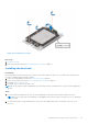


Table Of Contents
- Dell EMC PowerEdge R6525 Installation and Service Manual
- Contents
- About this document
- System overview
- Initial system setup and configuration
- Installing and removing system components
- Safety instructions
- Before working inside your system
- After working inside your system
- Recommended tools
- Cable routing
- RIO card
- Tube clip
- Optional front bezel
- System cover
- Drive backplane cover
- Control panel
- VGA module
- Air shroud
- Cooling fan
- Drives
- Drive backplane
- Rear drive module
- Front PERC module
- System memory
- Processor and heat sink
- Expansion cards and expansion card risers
- Optional serial COM port
- Optional IDSDM module
- MicroSD card
- M.2 SSD module
- BOSS S2 card (optional)
- System battery
- Optional internal USB card
- Intrusion switch module
- Optional OCP card
- Power supply unit
- Trusted Platform Module
- System board
- LOM card and rear I/O board
- Upgrade Kits
- Jumpers and connectors
- System diagnostics and indicator codes
- Getting help
- Documentation resources

NOTE: Liquid detection cable must be placed underneath the cooling tubes to ensure it does not interfere with the PCIe
risers
3. Route the liquid cooling tubes through the rear exit point next to the I/O function panel. Ensure the routing follows the
numbered labels on the tube and liquid cooling ring holder (1, 2).
4. Connect the liquid cooling detection cable to the RIO connector.
5. Insert the rubber rings on the tubes on to the rubber holder.
NOTE: The numbers on the image do not depict the exact steps. The numbers are for representation of sequence.
6. Using a Phillips #1 screwdriver, tighten the captive screw on the liquid cooling ring holder to secure it in place.
7. Route the liquid cooling tubes and liquid cooling detection cable along side PSU 2 and secure them with the tube clip.
Figure 83. Installing the liquid cooling heat sink modules
Next steps
1. Remove liquid cooling riser 3.
2. Install the air shroud.
3. Install the system cover.
4. Follow the procedure listed in the After working inside your system on page 27.
Expansion cards and expansion card risers
NOTE:
A system event entry is logged in the iDRAC Lifecycle Controller if an expansion card riser is not supported or
missing. It does not prevent your system from turning on. However, if a F1/F2 pause occurs with an error message,
86 Installing and removing system components