Dell EMC PowerEdge R6525 Installation and Service Manual Regulatory Model: E67S Regulatory Type: E67S001 June 2021 Rev.
Notes, cautions, and warnings NOTE: A NOTE indicates important information that helps you make better use of your product. CAUTION: A CAUTION indicates either potential damage to hardware or loss of data and tells you how to avoid the problem. WARNING: A WARNING indicates a potential for property damage, personal injury, or death. © 2019 - 2020 Dell Inc. or its subsidiaries. All rights reserved. Dell, EMC, and other trademarks are trademarks of Dell Inc. or its subsidiaries.
Contents Chapter 1: About this document.................................................................................................... 7 Chapter 2: System overview..........................................................................................................8 Front view of the system...................................................................................................................................................8 Left control panel view........................................
Removing the right control panel............................................................................................................................ 44 Installing the right control panel.............................................................................................................................. 45 Removing the left control panel..............................................................................................................................
Optional serial COM port................................................................................................................................................115 Removing the serial COM port................................................................................................................................115 Installing the serial COM port..................................................................................................................................
Internal USB card kit.......................................................................................................................................................154 Serial COM port kit......................................................................................................................................................... 154 Chapter 6: Jumpers and connectors...........................................................................................155 System board connectors........
1 About this document This document provides an overview about the system, information about installing and replacing components, technical specifications, diagnostic tools, and guidelines to be followed while installing certain components.
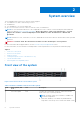
2 System overview The PowerEdge R6525 system is a 1U rack server that supports: ● Two AMD EPYC TM 7002 or 7003 series processors ● 32 DIMM slots ● Two redundant AC or DC power supply units ● Up to 4 x 3.5-inch, 8 x 2.5-inch, or 10 x 2.5-inch SAS, SATA, or NVMe drives. NOTE: For more information about how to hot swap NVMe PCIe SSD U.2 device, see the Dell Express Flash NVMe PCIe SSD User's Guide at https://www.dell.
Table 1. Features available on the front of the system (continued) Item Ports, panels, and slots Icon Description system health LED (Chassis health and system ID) bar. For more information, see the Status LED indicators section. ● Quick Sync 2 (wireless): Indicates a Quick Sync enabled system. The Quick Sync feature is optional. This feature allows management of the system by using mobile devices that are called as OpenManage Mobile (OMM) feature.
Table 2. Features available on the front of the system (continued) Item Ports, panels, and slots Icon Description various system level diagnostic and error information that can be used in troubleshooting the system. For more information, see the iDRAC User's Guide available at https://www.dell.com/idracmanuals 2 Drive (8) N/A Enables you to install drives that are supported on your system. For more information about drives, see the www.dell.com/ poweredgemanuals section.
Table 3. Features available on the front of the system (continued) Item Ports, panels, and slots 3 VGA port 4 Right control panel 5 Information tag Icon Description Enables you to connect a display device to the system. For more information, see the www.dell.com/poweredgemanuals section. N/A Contains the power button, USB port, iDRAC Direct micro port, and the iDRAC Direct status LED.
Table 4. Left control panel (continued) Item Indicator, button, or connector Icon Description firmware inventory and various system level diagnostic/error information that can be used in troubleshooting the system. You can access system inventory, Dell Lifecycle Controller logs or system logs, system health status, and also configure iDRAC, BIOS, and networking parameters.
Table 5. Right control panel (continued) Item Indicator or button Icon Description should not exceed 3 ft (0.91 meters). Quality of the cable might affect performance. NOTE: For more information about the ports, see the www.dell.com/poweredgemanuals section. Rear view of the system Figure 7. Rear view of the 10 x 2.5-inch drive system Table 6.
Table 6. Rear view of the system (continued) Item Ports, panels, or slots Icon Description ● To reset iDRAC using system ID, ensure that the system ID button is enabled in the iDRAC setup. ● If the system stops responding during POST, press and hold the system ID button (for more than 5 seconds) to enter the BIOS progress mode. 10 OCP NIC port (optional) 11 NIC port (2) 12 BOSS S2 card (optional) N/A This port supports OCP 3.0.
Table 7. Rear view of the system (continued) Item Ports, panels, or slots Icon Description 9 iDRAC dedicated port Enables you to remotely access iDRAC. For more information, see the iDRAC User’s Guide at www.dell.com/ poweredgemanuals. 10 System identification button Press the system ID button: ● To locate a particular system within a rack. ● To turn the system ID on or off. To reset iDRAC, press and hold the button for more than 16 seconds.
Table 8. Rear view of the system (continued) Item Ports, panels, or slots Icon Description 7 USB 3.0 port (1) This port is USB 3.0-compliant. 8 iDRAC dedicated port Enables you to remotely access iDRAC. For more information, see the iDRAC User’s Guide at www.dell.com/ poweredgemanuals. 9 System identification button Press the system ID button: ● To locate a particular system within a rack. ● To turn the system ID on or off. To reset iDRAC, press and hold the button for more than 16 seconds.
Inside the system Figure 10. Inside the system 1. 3. 5. 7. 9. 11. 13. 15. Drive backplane Dual fan module (4) Memory DIMM socket for processor 2 (B1) Riser 3 Power supply unit (PSU 2) IDSDM/Internal USB card port Riser 2 Memory DIMM socket for processor 1 (A1) 2. 4. 6. 8. 10. 12. 14. 16.
Figure 11. Locating the Express Service Code and Service tag 1. 2. 3. 4. 5. Information tag (front view) Information tag (back view) OpenManage Mobile (OMM) label iDRAC MAC address and iDRAC secure password label Service Tag, Express Service Code, QRL label The Mini Enterprise Service Tag (MEST) label is located on the rear of the system that includes Service Tag (ST), Express Service Code (Exp Svc Code), and Manufacture Date (Mfg. Date).
Figure 12.
Figure 13.
Figure 14. LED behavior, configuration and layout, express service tag Rail sizing and rack compatibility matrix For specific information about the rail solutions compatible with your system, see the Dell EMC Enterprise Systems Rail Sizing and Rack Compatibility Matrix available at https://i.dell.com/sites/csdocuments/Business_solutions_engineeringDocs_Documents/en/rail-rack-matrix.pdf.
3 Initial system setup and configuration This section describes the tasks for initial setup and configuration of the Dell EMC system. The sections provide general steps that you must complete to set up the system and the reference guides for detailed information. Topics: • • • Setting up the system iDRAC configuration Resources to install operating system Setting up the system Perform the following steps to set up the system: Steps 1. Unpack the system. 2. Install the system into the rack.
Table 9. Interfaces to set up iDRAC IP address (continued) Interface Documentation links see KB article https://www.dell.com/support/article/ sln308699. OpenManage Deployment Toolkit OpenManage Deployment Toolkit User's Guide available at https://www.dell.com/openmanagemanuals > Open Manage Deployment Toolkit. Lifecycle Controller Lifecycle Controller User’s Guide at https://www.dell.com/ idracmanuals or for system specific Lifecycle Controller User’s Guide, go to https://www.dell.
Resources to install operating system If the system is shipped without an operating system, you can install a supported operating system by using one of the resources provided in the table. For information about how to install the operating system, see the documentation links provided in the table. Table 10. Resources to install the operating system Resource Documentation links iDRAC Integrated Dell Remote Access Controller User's Guide at https://www.dell.
Table 12. Options to download and install OS drivers Option Documentation Dell EMC support site Downloading drivers and firmware section. iDRAC virtual media Integrated Dell Remote Access Controller User's Guide at https://www.dell.com/idracmanuals or for system specific Integrated Dell Remote Access Controller User's Guide, go to https://www.dell.com/poweredgemanuals > Product Support page of your system > Manuals & documents.
4 Installing and removing system components Topics: • • • • • • • • • • • • • • • • • • • • • • • • • • • • • • • • • • Safety instructions Before working inside your system After working inside your system Recommended tools Cable routing RIO card Tube clip Optional front bezel System cover Drive backplane cover Control panel VGA module Air shroud Cooling fan Drives Drive backplane Rear drive module Front PERC module System memory Processor and heat sink Expansion cards and expansion card risers Optional s
CAUTION: To ensure proper operation and cooling, all system bays and fans must be always populated with a component or a blank. NOTE: It is recommended that you always use an antistatic mat and antistatic strap while working on components inside the system. NOTE: While replacing the hot swappable PSU, after next server boot; the new PSU automatically updates to the same firmware and configuration of the replaced one.
● Tyco Electronics 58433-3 or equivalent ● Wire-stripper pliers to remove insulation from size 10 AWG solid or stranded, insulated copper wire NOTE: Use alpha wire part number 3080 or equivalent (65/30 stranding). Cable routing Figure 15. 4 x 3.5-inch SAS with one processor and front PERC module Figure 16. 4 x 3.
Figure 17. 4 x 3.5-inch SATA with no PERC module Figure 18. 8 x 2.
Figure 19. 4 x 3.5-inch SAS with 2 x 2.5-inch SAS rear drives Figure 20. 4 x 3.5-inch SAS with 2 x 2.
Figure 21. 10 x 2.5-inch SAS with 2 x 2.5-inch SAS rear drives Figure 22. 10 x 2.
Figure 23. 10 x 2.5-inch Universal backplane Figure 24. 10 x 2.
Figure 25. 10 X 2.5-inch NVMe (64 mode) Figure 26. 10 X 2.5-inch SAS with 2 x 2.
Figure 27. 10 x 2.5-inch SAS with 2 x 2.5-inch NVMe drive Figure 28. 8 x 2.5- inch NVMe RAID RIO card Removing the Rear Input Output (RIO) card Prerequisites 1. Follow the safety guidelines listed in the Safety instructions on page 26. 2. Follow the procedure listed in the Before working inside your system on page 27.
3. Remove the system board. Steps 1. Using a Phillips #2 screwdriver, remove the screws that secure the RIO card to the system board. 2. Holding the edges, pull the RIO card to disconnect from the connector on the system board. Figure 29. Removing the RIO card Next steps 1. Replace the RIO card. Installing the RIO card Prerequisites 1. 2. 3. 4. Follow the safety guidelines listed in the Safety instructions on page 26. Follow the procedure listed in the Before working inside your system on page 27.
Figure 30. Installing the RIO card Next steps 1. Install the system board. 2. Follow the procedure listed in After working inside your system on page 27. Tube clip Removing the tube clip Prerequisites 1. Follow the safety guidelines listed in the Safety instructions on page 26. 2. Follow the procedure listed in the Before working inside your system on page 27. 3. Remove the system cover. Steps Using a Phillips #2 screwdriver, loosen the screw that is securing the tube clip and remove it from the chassis.
Figure 31. Removing the tube clip Next steps 1. Replace the tube clip. Installing the tube clip Prerequisites 1. Follow the safety guidelines listed in the Safety instructions on page 26. 2. Follow the procedure listed in the Before working inside your system on page 27. 3. Remove the system cover. Steps 1. Place the tube clip onto the chassis according to the guide pins. 2. Using a Phillips #2 screwdriver, secure the tube clip to the chassis with the screw.
Figure 32. Installing the tube clip Next steps 1. Install the system cover. 2. Follow the procedure listed in After working inside your system on page 27. Optional front bezel Removing the front bezel The procedure to remove the front bezel with and without the LCD panel is the same. Prerequisites 1. Follow the safety guidelines listed in the Safety instructions on page 26. 2. Keep the bezel key handy. NOTE: The bezel key is part of the LCD bezel package. Steps 1. Unlock the bezel. 2.
Figure 33. Removing the front bezel Next steps 1. Replace the front bezel. Installing the front bezel The procedure to install the front bezel with and without the LCD panel is the same. Prerequisites 1. Follow the safety guidelines listed in the Safety instructions on page 26. 2. Locate and remove the bezel key. NOTE: The bezel key is part of the LCD bezel package. Steps 1. Align and insert the tabs on the bezel into the slots on the system. 2. Press the bezel until the release button clicks in place. 3.
Figure 34. Installing the front bezel System cover Removing the system cover Prerequisites 1. Follow the safety guidelines listed in the Safety instructions on page 26. 2. Power off the system, and any attached peripherals. 3. Disconnect the system from the electrical outlet and peripherals. Steps 1. Using a 1/4-inch flat head or a Phillips #2 screwdriver rotate the lock counterclockwise to the unlock position. 2. Lift the release latch until the system cover slides back. 3. Lift the cover from the system.
Figure 35. Removing the system cover Next steps 1. Replace the system cover. Installing the system cover Prerequisites 1. Follow the safety guidelines listed in the Safety instructions on page 26. 2. Follow the procedure listed in Before working inside your system on page 27. 3. Ensure that all internal cables are connected and routed properly, and no tools or extra parts are left inside the system. Steps 1. Align the tabs on the system cover with the guide slots on the system and slide the system cover.
Figure 36. Installing the system cover Next steps 1. Follow the procedure listed in After working inside your system on page 27. Drive backplane cover Removing the drive backplane cover Prerequisites 1. Follow the safety guidelines listed in the Safety instructions on page 26. 2. Follow the procedure listed in Before working inside your system on page 27. Steps 1. Slide the backplane cover in the direction of the arrows marked on the drive backplane cover. 2. Lift the backplane cover from the system.
Figure 37. Removing the drive backplane cover Next steps 1. Replace the drive backplane cover. Installing the drive backplane cover Prerequisites 1. Follow the safety guidelines listed in the Safety instructions on page 26. Steps 1. Align the drive backplane cover with the guide slots on the system. 2. Slide the drive backplane cover to the front of the system until the drive backplane cover fits into place. Figure 38.
Next steps 1. Follow the procedure listed in After working inside your system on page 27. Control panel Removing the right control panel Prerequisites 1. 2. 3. 4. Follow the safety guidelines listed in the Safety instructions on page 26. Follow the procedure listed in the Before working inside your system on page 27. Remove the drive backplane cover. If installed, remove the air shroud. Steps 1. Disconnect the right control panel cable from the connector on the system board. 2.
Installing the right control panel Prerequisites 1. Follow the safety guidelines listed in the Safety instructions on page 26. 2. Follow the procedure listed in Before working inside your system on page 27. Steps 1. Align and slide the right control panel in the slot on the system. 2. Connect the right control panel cable to the connector on the system board. 3. Route the right control panel cable through the side wall of the system. Close the cable latch and slide the cable into the clip.
3. If installed, remove the air shroud. Steps 1. Disconnect the control panel cable from the connector on the system board. 2. Lift the latch to release the control panel cable and slide the cable from the clip. NOTE: Observe the routing of the cable as you remove it from the system. 3. Using the Phillips #1 screwdriver, remove the screws that secure the left control panel to the system. 4. Hold the left control panel cable, and slide the left control panel out of the system.
4. Using the Phillips #1 screwdriver, tighten the screws to secure the left control panel to the system. Figure 42. Installing the left control panel Next steps 1. Install the drive backplane cover. 2. If removed, install the air shroud. 3. Follow the procedure listed in After working inside your system on page 27. VGA module Removing the VGA module Prerequisites 1. 2. 3. 4. 5. 6. 7. Follow the safety guidelines listed in the Safety instructions on page 26.
NOTE: The numbers on the image do not depict the exact steps. The numbers are for representation of sequence. Figure 43. Removing the VGA module Next steps 1. Replace the VGA module. Installing the VGA module Prerequisites 1. 2. 3. 4. 5. 6. 7. Follow the safety guidelines listed in the Safety instructions on page 26. Follow the procedure listed in the Before working inside your system on page 27. If installed, remove the front bezel. Remove the backplane cover. If installed, remove the air shroud.
Figure 44. Installing the VGA module Next steps 1. 2. 3. 4. 5. 6. Route the VGA cable, close the cable latch, and connect the VGA cable to the connector on the system board. Route and connect the right control panel cable. If removed, install the air shroud. Install the backplane cover. If installed, install the front bezel. Follow the procedure listed in the After working inside your system on page 27.
Air shroud Removing the air shroud Prerequisites CAUTION: Never operate your system with the air shroud removed. The system may get overheated quickly, resulting in shutdown of the system and loss of data. 1. Follow the safety guidelines listed in the Safety instructions on page 26. 2. Follow the procedure listed in Before working inside your system on page 27. Steps 1. Hold the edges of the air shroud, and lift the air shroud out of the system.
Figure 46. Removing the air shroud from the rear drive module Next steps 1. Replace the air shroud. Installing the air shroud Prerequisites 1. Follow the safety guidelines listed in the Safety instructions on page 26. 2. Follow the procedure listed in Before working inside your system on page 27. Steps 1. Align the slot on the air shroud with the standoff on the system. 2. Lower the air shroud into the system until it is firmly seated.
Figure 47. Installing the air shroud 3. For the air shroud on the rear drive module, lower the air shroud into the rear drive module until it is firmly seated. Figure 48. Installing the air shroud on the rear drive module Next steps 1. Follow the procedure listed in After working inside your system on page 27.
Cooling fan Removing a cooling fan module Prerequisites 1. Follow the safety guidelines listed in the Safety instructions on page 26. 2. Follow the procedure listed in Before working inside your system on page 27. 3. If installed, remove the air shroud. Steps Holding the orange and black edges on the fan module, lift the cooling fan module horizontally to disconnect from the connector on the system board.
NOTE: The procedure to install standard, high performance (silver grade), or high performance (gold grade) fan module is same. 2. Press the touch point on the cooling fan module until firmly connected. Figure 50. Installing a cooling fan module Next steps 1. If removed, install the air shroud. 2. Follow the procedure listed in After working inside your system on page 27. Drives Removing a drive blank Prerequisites 1. Follow the safety guidelines listed in the Safety instructions on page 26. 2.
Figure 51. Removing a drive blank Next steps 1. Installing a drive or replace the drive blank. Installing a drive blank Prerequisites 1. Follow the safety guidelines listed in the Safety instructions on page 26. 2. If installed, remove the front bezel. Steps Insert the drive blank into the drive slot until the release button clicks into place. Figure 52. Installing a drive blank Next steps 1. If removed, install the front bezel. Removing the drive carrier Prerequisites 1.
CAUTION: Before attempting to remove or install a drive while the system is running, see the documentation for the storage controller card to ensure that the host adapter is configured correctly to support drive removal and insertion. CAUTION: To prevent data loss, ensure that your operating system supports drive installation. For more information about the drives installation or uninstallation requirements, see the operating system's user guide. Steps 1.
NOTE: Ensure that the drive carrier's release handle is in the open position before inserting the carrier into the slot. 1. Follow the safety guidelines listed in the Safety instructions on page 26. 2. If installed, remove the front bezel. 3. Remove the drive carrier or remove the drive blank when you want to assemble the drives in to the system. Steps 1. Slide the drive carrier into the drive slot. 2. Close the drive carrier release handle to lock the drive in place. Figure 54.
2. Lift the drive out of the drive carrier. Figure 55. Removing the drive from the drive carrier Next steps Install the drive into the drive carrier. Installing the drive into the drive carrier Prerequisites 1. Follow the safety guidelines listed in the Safety instructions on page 26. 2. If installed, remove the front bezel. 3. Remove the drive blank. Steps 1. Insert the drive into the drive carrier with the drive connector facing towards the rear of the carrier. 2.
Figure 56. Installing a drive into the drive carrier Next steps 1. Install the drive carrier. 2. If removed, install the front bezel. Drive backplane Drive backplane Depending on your system configuration, the drive backplanes supported are listed here: Table 13. Supported backplane options System Supported hard drives options 3.5-inch (x4) SAS, SATA backplane PowerEdge R6525 2.5-inch (x8) SAS or SATA backplane 2.5-inch (x10) SAS, SATA or NVMe backplane 2.
Figure 57. 4 x 3.5-inch drive backplane 1. BP_PWR_1 (backplane power and signal cable to system board) Figure 58. 8 x 2.5-inch drive backplane 1. BP_PWR_1 (backplane power and signal cable to system board) Figure 59. 10 x 2.5-inch drive backplane 1. DST_SA2 (backplane to front PERC) 3. DST_PA2 (PCIe/NVMe connector) 5. BP_PWR_1 (backplane power and signal cable to system board) 7. DST_PB1 (PCIe/NVMe connector) 2. DST_PB2 (PCIe/NVMe connector) 4. DST_SA1 (PERC to backplane) 6.
Steps 1. Loosen the captive screw on the cable guiding latch and lift the latch to remove the cables. 2. Disconnect the drive backplane cable from the connector on the system board. 3. Press the blue release tabs to disengage the drive backplane from the hooks on the system. 4. Lift and pull the drive backplane out of the system. NOTE: To avoid damaging the backplane, ensure that you move the control panel cables from the cable routing clips before removing the backplane.
NOTE: To avoid damaging the backplane, ensure to move the control panel cables from the cable routing clips before removing the backplane. NOTE: Route the cable properly when you replace it to prevent the cable from being pinched or crimped. Steps 1. Use the guides on the system as guides to align the slots on the backplane. 2. Insert the backplane into the guides and lower the backplane until the blue release tabs clicks into place. NOTE: The numbers on the image do not depict the exact steps.
Rear drive module Removing the rear drive module Prerequisites 1. 2. 3. 4. 5. 6. Follow the safety guidelines listed in Safety instructions on page 26. Follow the procedure listed in Before working inside your system on page 27. Remove the air shroud. Remove the rear drives. Disconnect all the cables from the rear drive module. If installed, remove the expansion card riser 3. Steps 1.
Figure 63. Removing the liquid cooling rear drive module Next steps 1. Replace the rear drive module. Installing the rear drive module Prerequisites 1. Follow the safety guidelines listed in Safety instructions on page 26. 2. Follow the procedure listed in Before working inside your system on page 27. 3. Remove the air shroud. Steps 1. Align the rear drive module with the guide on the system board. 2. Lower the rear drive module and slide till it clicks. 3.
Figure 64. Installing the rear drive module Figure 65.
Next steps 1. 2. 3. 4. 5. If removed, install the expansion card riser 3. Connect all the cables to the rear drive module. Install the rear drives. Install the air shroud. Follow the procedure listed in After working inside your system. Front PERC module Removing the front mounting front PERC module Prerequisites 1. 2. 3. 4. 5. Follow the safety guidelines listed in the Safety instructions on page 26. Follow the procedure listed in the Before working inside your system on page 27.
Figure 66. Removing the front mounting front PERC module Next steps 1. Replace the front mounting front PERC module. Installing the front mounting front PERC module Prerequisites 1. 2. 3. 4. 5. Follow the safety guidelines listed in the Safety instructions on page 26. Follow the procedure listed in Before working inside your system on page 27. Remove the drive backplane cover. If installed, remove the air shroud. Route the cable properly to prevent the cable from being pinched or crimped. Steps 1.
Figure 67. Installing the front mounting front PERC module Next steps 1. 2. 3. 4. Reconnect all the required cables. If removed, install the air shroud. Install the drive backplane cover. Follow the procedure listed in After working inside your system on page 27. Removing the rear mounting front PERC module Prerequisites 1. 2. 3. 4. 5. 6. Follow the safety guidelines listed in the Safety instructions on page 26. Follow the procedure listed in the Before working inside your system on page 27.
Figure 68. Removing the rear mounting front PERC module Next steps 1. Replace the rear mounting front PERC module. Installing the rear mounting front PERC module Prerequisites 1. 2. 3. 4. 5. 6. Follow the safety guidelines listed in the Safety instructions on page 26. Follow the procedure listed in Before working inside your system on page 27. Remove the drive backplane cover. If installed, remove the air shroud. Remove the drive backplane.
Figure 69. Installing the rear mounting front PERC module Next steps 1. 2. 3. 4. Install the drive backplane. If removed, install the air shroud. Install the drive backplane cover. Follow the procedure listed in After working inside your system on page 27. System memory System memory guidelines The PowerEdge R6525 system supports DDR4 registered DIMMs (RDIMMs) and Load Reduced DIMM (LRDIMMs). System memory holds the instructions that are started by the processor.
Figure 70. Memory channels Memory channels are organized as follows: Table 14.
Table 15. Supported memory matrix (continued) DIMM type Rank Capacity DIMM rated voltage and speed Operating Speed 1 DIMM per channel (DPC) DDR4 (1.2 V), 3200 3200 MT/s MT/s 2 DIMMs per channel (DPC) 2933 MT/s General memory module installation guidelines To ensure optimal performance of your system, observe the following general guidelines when configuring your system memory.
Non-uniform memory access (NUMA) is a memory design used in multi-processing, where the memory access time depends on the memory location relative to the processor. In NUMA, a processor can access its own local memory faster than the non-local memory. NUMA nodes per socket (NPS) is a new feature added that allows you to configure the memory NUMA domains per socket. The configuration can consist of one whole domain (NPS1), two domains (NPS2), or four domains (NPS4).
Table 17. Supported NPS modes by Processors (continued) Model Number NPS modes supported 7763 4, 2, 1, 0 Table 18. Optimal NPS configuration Number of DIMMs per processor NPS 0 1 2 4 1 X 2 X 3 X 4 X 5 X 6 X 7 X 8 X X 9 X 10 X 11 X 12 X 13 X 14 X 15 X 16 ● ● ● ● ● ● X X Recommended NPS setting is marked by X that indicate optimal performance. NPS0 is only available for dual processor systems and is the preferred setting.
NOTE: An exception is allowed when system has 4-channels populated [C, D, G, H] with equal memory allowing the system to enter NPS1 mode even though all the 8 channels are not populated. ● NPS0: Sixteen channel interleaving (dual processor) ○ This interleaves all 16 channels in a dual processor system. ○ All channels in a system require equal memory modules populated. ○ Dual processor systems create a single NUMA node for the system. Removing a memory module Prerequisites 1.
3. If installed, remove the air shroud. WARNING: The memory modules are hot to touch for some time after the system has been powered down. Allow the memory modules to cool before handling them. Handle the memory modules by the card edges and avoid touching the components or metallic contacts on the memory module. Steps 1. Locate the appropriate memory module socket. CAUTION: Handle each memory module only by the card edges, ensuring not to touch the middle of the memory module or metallic contacts. 2.
3. To verify if the memory module has been installed properly, press F2 and navigate to System Setup Main Menu > System BIOS > Memory Settings. In the Memory Settings screen, the System Memory Size must reflect the updated capacity of the installed memory. 4. If the System Memory Size is incorrect, one or more of the memory modules may not be installed properly. Ensure that the memory modules are firmly seated in their sockets. 5. Run the system memory test in system diagnostics.
Next steps 1. If you are uninstalling a faulty heat sink, replace the heat sink, else remove the processor. Removing the liquid cooling heat sink modules Prerequisites 1. 2. 3. 4. Follow the safety guidelines listed in the Safety instructions on page 26. Follow the procedure listed in the Before working inside your system on page 27. Remove the system cover. Remove the air shroud. WARNING: The heat sink and processor are too hot to touch for some time after the system has been powered off.
Figure 74. Removing the liquid cooling heat sink modules Next steps 1. If you are uninstalling a faulty liquid cooling heat sink module, replace the liquid cooling heat sink modules, else remove the processor. Removing the processor Prerequisites WARNING: The heat sink may be hot to touch for some time after the system has been powered off. Allow the heat sink to cool before removing it. 1. Follow the safety guidelines listed in the Safety instructions on page 26. 2.
Figure 75. Removing screws on the force plate 2. Release the processor socket rail frame by lifting the blue latches. Figure 76. Lifting the rail frame 3. Holding the blue tab on the processor tray, slide the tray out of the rail frame.
Figure 77. Removing the processor tray Next steps 1. Replace the processor. Installing the processor Prerequisites 1. Follow the safety guidelines listed in the Safety instructions on page 26. 2. Follow the procedure listed in Before working inside your system on page 27. 3. Remove the heat sink. Steps 1. Holding the blue tab on the processor tray, slide the tray into the processor socket rail frame until firmly seated.
Figure 78. Placing the processor tray into the rail frame 2. Push the rail frame down until the blue latches lock into place. Figure 79. Closing the rail frame 3. Secure the force plate to the processor socket base by tightening the screws in the sequence 1, 2, and 3. When all three screws are fully threaded, the socket is then actuated. The three screws are tightened to a torque value of 12.0 ± 1.2 lbf-in. NOTE: The screw numbers are marked on the force plate.
Figure 80. Securing the force plate Next steps 1. Install the heat sink. 2. Follow the procedure listed in After working inside your system on page 27. Installing the heat sink Prerequisites Never uninstall the heat sink from a processor unless you intend to replace the processor or system board. The heat sink is necessary to maintain proper thermal conditions. 1. Follow the safety guidelines listed in the Safety instructions on page 26. 2.
Figure 81. Applying thermal grease CAUTION: Applying too much thermal grease can result in excess grease coming in contact with and contaminating the processor socket. NOTE: The thermal grease syringe is intended for single use only. Dispose of the syringe after you use it. 3. Align the screws on the heat sink with the standoff screws on the system board. NOTE: The A1 extrusion on the L-type heat sink should face towards the system side. 4.
Figure 82. Installing a heat sink Next steps 1. If removed, install the air shroud. 2. Follow the procedure listed in the After working inside your system on page 27. Installing the liquid cooling heat sink modules Prerequisites Never uninstall the heat sink from a processor unless you intend to replace the processor or system board. The heat sink is necessary to maintain proper thermal conditions. 1. 2. 3. 4. 5. 6. 7. Follow the safety guidelines listed in the Safety instructions on page 26.
NOTE: Liquid detection cable must be placed underneath the cooling tubes to ensure it does not interfere with the PCIe risers 3. Route the liquid cooling tubes through the rear exit point next to the I/O function panel. Ensure the routing follows the numbered labels on the tube and liquid cooling ring holder (1, 2). 4. Connect the liquid cooling detection cable to the RIO connector. 5. Insert the rubber rings on the tubes on to the rubber holder. NOTE: The numbers on the image do not depict the exact steps.
see Troubleshooting expansion cards section in the Dell EMC PowerEdge Servers Troubleshooting Guide at www.dell.com/ poweredgemanuals. Expansion card installation guidelines The following table describes the supported expansion cards: Table 19.
Table 21.
Table 22.
Table 23.
Table 24.
Table 25.
Table 26.
Table 27.
Table 27.
Table 27.
Table 27. Configuration 6: R1D+R2A+R3A (continued) Card Type Supplier Category Card Priority Slot Priority CRD,NTWK,INTL,OCP3 ,1G,4P,BT Intel OCP: 1Gb 10200 INT ASSY,CRD,CTL,H840,8 GA,FHV2,18F FOXCONN External Adapter 10500 Not supported ASSY,CRD,CTL,H840,8 GAD,LPV2,18 FOXCONN External Adapter 10600 2, 1, 3 PWA,CTL,12GB-SASHBA,ADPT,FH FOXCONN External Adapter 10700 Not supported PWA,CTL,12GB-SASHBA,ADPT,LPF FOXCONN External Adapter 10800 2, 1, 3 ASSY,CRD,CTL,BOSS.
Table 28.
Table 28.
Table 28.
Table 28.
Table 28.
Table 28. Configuration 7: R1D+R2B+R3A (continued) Card type Supplier Category Card Priority Slot Priority Bracket Height Max # of Allowed Cards KIT,CRD,NVME, SAMSUNG 6.4,HHHL,PM17 25B PCIE SSD 11900 3 LP/FH 1 KIT,CRD,NVME, SAMSUNG 1.6,HHHL,PM17 35 PCIE SSD 12000 3 LP/FH 1 KIT,CRD,NVME, SAMSUNG 1.6,HHHL,PM17 35,O PCIE SSD 12100 3 LP/FH 1 KIT,CRD,NVME, SAMSUNG 3.2,HHHL,PM17 35 PCIE SSD 12200 3 LP/FH 1 KIT,CRD,NVME, SAMSUNG 3.
Figure 84. Removing the expansion card riser (Riser 1) 2. For Riser 2 and liquid cooling Riser 2, press the blue button on the riser, and holding the touch points lift the expansion card riser from the riser connector on the system board. NOTE: The numbers on the image do not depict the exact steps. The numbers are for representation of sequence. Figure 85.
Figure 86. Removing the liquid cooling expansion card riser (liquid cooling Riser 2) 3. For Riser 3 and liquid cooling Riser 3, press the blue button on the riser, and lift the expansion card riser from the riser connector on the system board. Figure 87.
Figure 88. Removing the liquid cooling expansion card riser (liquid cooling Riser 3) 4. For Riser 4, press the blue tab on the riser, and holding the touch point lift the expansion card riser from the riser connector on the system board.
Figure 89. Removing the expansion card riser (Riser 4) Next steps 1. Replace the expansion card riser. Installing the expansion card risers Prerequisites 1. Follow the safety guidelines listed in the Safety instructions on page 26. 2. Follow the procedure listed in Before working inside your system on page 27. 3. If removed, install the expansion cards into the expansion card risers. Steps 1.
Figure 90. Installing the expansion card riser (Riser 1) Figure 91.
Figure 92. Installing the liquid cooling expansion card riser (liquid cooling Riser 2) Figure 93.
Figure 94.
Figure 95. Installing the expansion card riser (Riser 4) Next steps 1. If required, re-connect the cables to the expansion card. 2. Follow the procedure listed in After working inside your system on page 27. 3. Install any device drivers required for the card as described in the documentation for the card. Removing expansion card from the expansion card riser Prerequisites 1. Follow the safety guidelines listed in the Safety instructions on page 26. 2.
Figure 96. Opening the card holder on the expansion card riser 2. Hold the expansion card by the edges and pull the card until the card edge connector disengages from the expansion card connector on the riser. NOTE: The numbers on the image do not depict the exact steps. The numbers are for representation of sequence. Figure 97.
3. If the expansion card is not going to be replaced, install a filler bracket and close the card retention latch. Figure 98. Installing the filler bracket Next steps 1. If applicable, install an expansion card into the expansion card riser. Installing an expansion card into the expansion card riser Prerequisites WARNING: Consumer-Grade GPU should not be installed or used in the Enterprise Server products. 1. Follow the safety guidelines listed in the Safety instructions on page 26. 2.
Figure 99. Removing the filler bracket 3. Hold the card by its edges, and align the card edge connector with the expansion card connector on the riser. 4. Insert the card edge connector firmly into the expansion card connector until the card is fully seated. 5. Close the expansion card retention latch. Figure 100.
NOTE: Push the black card holder to hold the card in the riser. Figure 101. Closing the card holder on the expansion card riser Next steps 1. If applicable, connect the cables to the expansion card. 2. Follow the procedure listed in After working inside your system on page 27. 3. Install any device drivers required for the card as described in the documentation for the card. Optional serial COM port Removing the serial COM port Prerequisites 1.
Figure 102. Removing the serial COM port Next steps 1. Replace the serial COM port. Installing the serial COM port Prerequisites 1. Follow the safety guidelines listed in the Safety instructions on page 26. 2. Follow the procedure listed in Before working inside your system on page 27. 3. Lift the expansion card riser and disconnect the serial COM port cable from the connector on the rear I/O board. Steps 1.
Figure 103. Installing the serial COM port Next steps 1. Install the expansion card riser. 2. Follow the procedure listed in After working inside your system on page 27. Optional IDSDM module Removing the IDSDM module Prerequisites 1. Follow the safety guidelines listed in the Safety instructions on page 26. 2. Follow the procedure listed in the Before working inside your system on page 27. 3. If you are replacing the IDSDM module, remove the MicroSD cards.
Figure 104. Removing the IDSDM module Next steps 1. Replace the IDSDM module. Installing the IDSDM module Prerequisites 1. Follow the safety guidelines listed in the Safety instructions on page 26. 2. Follow the procedure listed in Before working inside your system on page 27. Steps 1. Locate the IDSDM connector on the system board. To locate IDSDM module, see the System board jumpers and connectors section. 2. Align IDSDM module with the connector on the system board. 3.
Figure 105. Installing the IDSDM module Next steps 1. Install the MicroSD cards. NOTE: Reinstall the MicroSD cards into the same slots based on the labels you had marked on the cards during removal. 2. Follow the procedure listed in After working inside your system on page 27. MicroSD card Removing the MicroSD card Prerequisites 1. Follow the safety guidelines listed in the Safety instructions on page 26. 2. Follow the procedure listed in the Before working inside your system on page 27. 3.
Figure 106. Removing the MicroSD card Next steps 1. Replace the MicroSD cards. Installing the MicroSD card Prerequisites 1. Follow the safety guidelines listed in the Safety instructions on page 26. 2. Follow the procedure listed in Before working inside your system on page 27. NOTE: To use an MicroSD card with your system, ensure that the Internal SD Card Port is enabled in System Setup.
Figure 107. Installing the MicroSD card Next steps 1. Install the IDSDM module. 2. Follow the procedure listed in After working inside your system on page 27. M.2 SSD module Removing the M.2 SSD module Prerequisites 1. Follow the safety guidelines listed in the Safety instructions on page 26. 2. Follow the procedure listed in the Before working inside your system on page 27. 3. Remove the BOSS card. The BOSS card removal is similar to removing expansion card from the expansion card riser. Steps 1.
Figure 108. Removing the M.2 SSD module Next steps 1. Replace the M.2 SSD module. Installing the M.2 SSD module Prerequisites 1. Follow the safety guidelines listed in the Safety instructions on page 26. 2. Follow the procedure listed in the Before working inside your system on page 27. 3. Remove the BOSS card. Removing BOSS card is similar to removing expansion card from the expansion card riser. Steps 1. Align the M.2 SSD module at an angle with the BOSS card connector. 2. Insert the M.
Figure 109. Installing the M.2 SSD module Next steps 1. Install the BOSS card. Installing the BOSS is similar to installing expansion card into the expansion card riser. 2. Follow the procedure listed in the After working inside your system on page 27. BOSS S2 card (optional) Removing the BOSS card filler Prerequisites Follow the safety guidelines listed in the Safety instructions on page 26. Steps Press and pull the BOSS card filler out from the BOSS module bay.
Figure 110. Removing the BOSS card filler Next steps 1. Replace the BOSS S2 controller card module or install the BOSS card filler. Installing the BOSS card filler Prerequisites 1. Follow the safety guidelines listed in the Safety instructions on page 26. Steps Align the BOSS card filler with the BOSS module bay and push it into the bay until it clicks into place.
Figure 111. Installing the BOSS card filler Removing the BOSS S2 controller card module Prerequisites 1. Follow the safety guidelines listed in the Safety instructions on page 26. 2. Follow the procedure listed in the Before working inside your system on page 27. Steps 1. Lift the retention latch to release the BOSS S2 card carrier. 2. Slide the BOSS S2 card carrier out from the BOSS S2 controller card module.
Figure 112. Removing the BOSS S2 card carrier 3. Using the Phillips #1 screwdriver remove the M3 x 0.5 x 4.5 mm screw that secures the M.2 SSD to the BOSS S2 card carrier. 4. Slide the M.2 SSD out and up from the BOSS S2 card carrier. Figure 113. Removing the M.2 SSD 5. Disconnect the BOSS power cable and BOSS signal cable from the system board. Using the Phillips #1 screwdriver remove the two M3 x 0.5 x 4.5 mm screws that secure the BOSS S2 controller card module on the BOSS module bay.
Figure 114. Removing the BOSS S2 controller card module 6. Remove the BOSS power cable and BOSS signal cable from the BOSS S2 controller card module. Figure 115. Removing the BOSS power cable and BOSS signal cable from the BOSS S2 controller card module 7. Using the Phillips #1 screwdriver, remove the M3 x 0.5 x 4.5 mm screw that secures the BOSS cover on the BOSS S2 controller card module. Slide the BOSS cover out from the BOSS S2 controller card module.
Figure 116. Removing the BOSS cover Next steps 1. Replace the BOSS S2 controller card module. Installing the BOSS S2 controller card Prerequisites 1. Follow the safety guidelines listed in the Safety instructions on page 26. 2. Follow the procedure listed in the Before working inside your system on page 27. Steps 1. Slide the BOSS cover on the BOSS S2 controller card module. Using the Phillips #1 screwdriver, secure the BOSS cover on the BOSS S2 controller card module with the M3 x 0.5 x 4.5 mm screw.
Figure 117. Installing the BOSS cover 2. Connect the BOSS power cable and BOSS signal cable to the BOSS S2 controller card module. Figure 118. Connecting the BOSS power cable and BOSS Signal cable to the BOSS S2 controller card module 3. Slide the BOSS S2 controller card module into the BOSS module bay until it is firmly seated. 4. Using the Phillips #1 screwdriver, secure the BOSS S2 controller card module on the BOSS module bay with the two M3 x 0.5 x 4.5 mm screws.
Figure 119. Installing the BOSS S2 controller card module 5. Align the M.2 SSD at an angle with the BOSS S2 card carrier. 6. Insert the M.2 SSD until it is firmly seated in the BOSS S2 card carrier. 7. Using the Phillips #1 screwdriver, secure the M.2 SSD on the BOSS S2 card carrier with the M3 x 0.5 x 4.5 mm screw. Figure 120. Installing the M.2 SSD 8. Slide the BOSS S2 card carrier into the BOSS S2 controller card module slot. 9. Close the BOSS S2 card carrier release latch to lock the carrier in place.
Figure 121. Installing the BOSS S2 card carrier Next steps 1. Follow the procedure listed in the After working inside your system on page 27. System battery Replacing the system battery Prerequisites WARNING: There is a danger of a new battery exploding if it is incorrectly installed. Replace the battery only with the same or equivalent type That is recommended by the manufacturer. Discard used batteries according to the manufacturer's instructions. See the Safety instructions.
Figure 122. Removing the system battery 2. To install a new system battery: a. Hold the battery with the positive side facing up and slide it under the securing tabs. b. Press the battery into the connector until it snaps into place. Figure 123. Installing the system battery Next steps 1. 2. 3. 4. Install the expansion card risers. If applicable, connect the cables to one or more expansion cards. Follow the procedure listed in After working inside your system on page 27.
d. To test the newly installed battery, remove the system from the enclosure for at least an hour. e. Reinstall the system into the enclosure after an hour. f. Enter the System Setup and if the time and date are still incorrect, see Getting help section. Optional internal USB card NOTE: To locate the internal USB port on the system board, see the System board jumpers and connectors section.
3. Remove the expansion card risers. Steps 1. Connect the USB key to the internal USB card. 2. Align the internal USB card with the connector on the system board and press firmly until the internal USB card is seated. Figure 125. Installing the internal USB card Next steps 1. Install the expansion card risers. 2. Follow the procedure listed in After working inside your system on page 27. 3. While booting, press F2 to enter System Setup and verify that the system detects the USB memory key.
Figure 126. Removing the intrusion switch module Next steps 1. Replace the intrusion switch module. Installing the intrusion switch module Prerequisites 1. Follow the safety guidelines listed in the Safety instructions on page 26. 2. Follow the procedure listed in Before working inside your system on page 27. 3. Remove the expansion card riser. NOTE: Ensure that you note the routing of the cables as you remove them from the system board.
Figure 127. Installing the intrusion switch module Next steps 1. Install the expansion card riser. 2. Follow the procedure listed in After working inside your system on page 27. Optional OCP card Removing the OCP card Prerequisites 1. Follow the safety guidelines listed in the Safety instructions on page 26. 2. Follow the procedure listed in the Before working inside your system on page 27. 3. Remove the expansion card riser. Steps 1. Open the blue latch to unlock the OCP card. 2.
Figure 128. Removing the OCP card Next steps 1. Replace the OCP card. Installing the OCP card Prerequisites 1. Follow the safety guidelines listed in the Safety instructions on page 26. 2. Follow the procedure listed in the Before working inside your system on page 27. 3. Remove the expansion card riser. Steps 1. Open the blue latch on the system board. 2. Slide the OCP card into the slot in the system. 3. Push until the OCP card is connected to the connector on the system board. 4.
Figure 129. Installing the OCP card Next steps 1. Install the expansion card riser 2. Follow the procedure listed in After working inside your system on page 27. Power supply unit NOTE: While replacing the hot swappable PSU, after next server boot; the new PSU automatically updates to the same firmware and configuration of the replaced one. For more information about the Part replacement configuration, see the Lifecycle Controller User's Guide at https://www.dell.
● If the load on the active PSU falls below 20 percent of PSU rated power wattage, then the redundant PSU is switched to the sleep state. You can configure the hot spare feature by using the iDRAC settings. For more information, see the iDRAC User’s Guide available at www.dell.com/poweredgemanuals. Removing a power supply unit blank Prerequisites Follow the safety guidelines listed in the Safety instructions on page 26. Steps Pull the blank out of the system.
Figure 130. Removing a power supply unit Next steps 1. Replace the PSU or install the PSU blank. Installing a power supply unit Prerequisites 1. Follow the safety guidelines listed in the Safety instructions on page 26. 2. For systems that support redundant PSU, ensure that both the PSUs are of the same type and have the same maximum output power. NOTE: The maximum output power (shown in watts) is listed on the PSU label. 3. Remove the PSU blank.
Figure 131. Installing a power supply unit Next steps 1. If you have unlatched or removed the cable management accessory, re-install or relatch it. For information about the cable management when the PSU is removed or installed while the system is in the rack, see the system’s cable management accessory documentation at https://www.dell.com/poweredgemanuals. 2. Connect the power cable to the PSU, and plug the cable into a power outlet.
2. Press to hold the module down and remove the screw using the security Torx 8-bit shipped with the TPM module. 3. Slide the TPM module out from its connector. 4. Push the plastic rivet away from the TPM connector and rotate it 90° counterclockwise to release it from the system board. 5. Pull the plastic rivet out of its slot on the system board. Installing the TPM Steps 1. To install the TPM, align the edge connectors on the TPM with the slot on the TPM connector. 2.
3. From the TPM Security option, select On. 4. Save the settings. 5. Restart your system. System board Removing the system board Prerequisites CAUTION: If you are using the Trusted Platform Module (TPM) with an encryption key, you may be prompted to create a recovery key during program or System Setup. Be sure to create and safely store this recovery key.
Figure 133. Removing the system board Next steps 1. Install the system board. Installing the system board Prerequisites NOTE: Before replacing the system board, replace the old iDRAC MAC address label in the Information tag with the iDRAC MAC address label of the replacement system board 1. Follow the safety guidelines listed in the Safety instructions on page 26. 2. Follow the procedure listed in Before working inside your system on page 27. 3.
Figure 134. Installing the system board Next steps 1. Replace the following components: a. Trusted Platform Module (TPM) NOTE: The TPM Module must be replaced only while installing new system board. b. IDSDM module (if installed) c. Internal USB card (if installed) d. Power supply units (PSU) e. OCP card (if installed) f. Processor g. Heat sink h. Memory modules i. Cooling fan modules j. Air shroud (if installed) 2. Reconnect all cables to the system board.
Restoring Service Tag using Easy Restore The Easy Restore feature allows you to restore your Service Tag, iDRAC license, UEFI configuration, and the system configuration data after replacing the system board. All data is backed up in a backup Flash drive device automatically. If BIOS detects a new system board, and the Service Tag in the backup Flash drive device is different, BIOS prompts the user to restore the backup information. About this task Below is a list of options available: 1.
Figure 135. Removing the LOM card and rear I/O board Next steps 1. Replace the LOM card and rear I/O board. Installing the LOM card and rear I/O board Prerequisites 1. Follow the safety guidelines listed in the Safety instructions on page 26. 2. Follow the procedure listed in the Before working inside your system on page 27. 3. Remove the system board. Steps 1. Align the connectors and slots on the LOM card or rear I/O board with the connector and standoffs on the system board. 2.
Figure 136. Installing the LOM card and rear I/O board Next steps 1. Install the system board. 2. Follow the procedure listed in After working inside your system on page 27.
5 Upgrade Kits The table lists the available After Point Of Sale [APOS] kits. Table 29. Upgrade kits Kits Part number Related links to service instructions Bezel JYPW8/MPW3H (LCD) See Installing the front bezel BOSS See Installing the M.
Table 30. BOSS S2 kit components R6525 (quantity) Components in kit 1 BOSS cover 3 M3 x 0.05 x 4.5 mm screws 1 BOSS signal cable 1 BOSS power cable 1 BOSS-S2 controller card module 1 or 2* BOSS-S2 card carrier 1 or 2* M.2 SSD 2 M.2 240 GB information label 2 M.2 480 GB information label 1 BOSS card filler 1 Tech sheet To remove the BOSS blank : 1. Power off the system and remove the system cover. 2. Using the Phillips #1 screwdriver, remove the M3 x 0.05 x 4.
Figure 138. Installing the BOSS blank To install the BOSS S2 controller card module: 1. Install the BOSS S2 controller card module. To install the BOSS S2 controller card module, see installing the BOSS S2 controller card module steps 1 to 3. 2. Install the M.2 SSD. To install the M.2 SSD, see installing the BOSS S2 controller card module steps 4 to 8. NOTE: Installing the BOSS S2 card carrier does not require the system to be powered off.
NOTE: The backplane firmware (greater than 2.84) with GEN4 enabled feature is not available now and is expected only later half of FY21. The PCIe Gen 4 NVMe enablement kit contains the components listed in the table. Table 31. PCIe Gen 4 NVMe enablement kit components Components Quantity 10 x 2.5-inch SAS/SATA to One backplane and three slimline cables 6 x 2.5-inch SAS/SATA + 4 NVMe 10 x 2.5-inch SAS/SATA to One backplane and five slimline cables 10 x 2.5-inch NVMe Replacing 10 x 2.
IDSDM kit The IDSDM kit contains one IDSDM card. For installation procedure of IDSDM, see installing the IDSDM modulesection. Figure 139.
Internal USB card kit The internal USB card kit contains one internal USB card. For installation of internal USB card, see installing the internal USB cardsection. Figure 140. Internal USB card port information Serial COM port kit The serial COM port kit contains the components listed in the table. Table 32. Serial COM port kit Components Quantity Werial COM port card 1 Cable 1 For installation procedure of the serial COM port, see www.dell.com/poweredgemanuals in the serial COM port section.
6 Jumpers and connectors This section provides essential and specific information about jumpers and switches. It also describes the connectors on the various boards in the system. Jumpers on the system board help to disable the system and reset the passwords. To install components and cables correctly, you must be able to identify the connectors on the system board. Topics: • • • System board connectors System board jumper settings Disabling a forgotten password System board connectors Figure 141.
Table 33. System board jumpers and connectors (continued) Item Connector Description 3. Coin cell battery Coin cell battery 4. OCP NIC 3.0 connector OCP NIC 3.0 connector 5. IO_RISER2_A (CPU1) IO_RISER2_B (CPU2) Riser 2 6. J_TPM TPM 7. SIG_PWR_0 (Rear BP) Backplane signal and power 0 8. LOM connector LOM connector 9. IDSDM/Internal USB connector IDSDM/Internal USB connector 10. MB_FRONT_VIDEO Front VGA 11. SIG_PWR_4 GPU power 12. SL8_CPU1_PA2 PCIe/NVMe connector 8 13.
Table 33. System board jumpers and connectors (continued) Item Connector Description 37. SL5_CPU2_PA4_SA1 PCIe/NVMe/SATA connector 5 38. IO_RISER4 (CPU2) Riser 4 39. SL6_CPU2_PB4 PCIe/NVMe connector 6 40. SIG_PWR_3 GPU power System board jumper settings For information about resetting the password jumper to disable a password, see the Disabling a forgotten password section. Table 34. System board jumper settings Jumper Setting PWRD_EN Description The BIOS password feature is enabled.
6. Power off the system. 7. Remove the system cover. 8. Move the jumper on the system board from pins 4 and 6 to pins 2 and 4. 9. Replace the system cover. 10. Reconnect the system to the electrical outlet and power on the system, and all the attached peripherals. 11. Assign a new system and/or setup password.
7 System diagnostics and indicator codes This section describes the diagnostic indicators on the system front panel display system status during system startup.
Table 35. Status LED indicators and descriptions (continued) Icon Description Condition Corrective action Electrical indicator The indicator turns solid amber if the system experiences an electrical error (for example, voltage out of range, or a failed power supply unit (PSU) or voltage regulator). Check the System Event Log or system messages for the specific issue. If it is due to a problem with the PSU, check the LED on the PSU. Reseat the PSU. If the problem persists, see the Getting help section.
iDRAC Quick Sync 2 indicator codes iDRAC Quick Sync 2 module (optional) is located on the left control panel of the system. Table 37. iDRAC Quick Sync 2 indicators and descriptions iDRAC Quick Sync 2 indicator Condition code Corrective action Off (default state) Indicates that the iDRAC Quick Sync 2 feature is powered off. Press the iDRAC Quick Sync 2 button to power on the iDRAC Quick Sync 2 feature. If the LED fails to power on, reseat the left control panel flex cable and check.
LCD panel The LCD panel provides system information, status, and error messages to indicate if the system is functioning correctly or requires attention. The LCD panel is used to configure or view the iDRAC IP address of the system. For information about the event and error messages generated by the system firmware and agents that monitor system components, go to qrl.dell.com > Look Up > Error Code, type the error code, and then click Look it up.. The LCD panel is available only on the optional front bezel.
c. Select the Home icon. d. On the Home screen, press the Select button to enter the main menu. Setup menu NOTE: When you select an option in the Setup menu, you must confirm the option before proceeding to the next action. Table 40. Setup menu Option Description iDRAC Select DHCP or Static IP to configure the network mode. If Static IP is selected, the available fields are IP, Subnet (Sub), and Gateway (Gtw). Select Setup DNS to enable DNS and to view domain addresses.
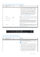
NIC indicator codes Each NIC on the back of the system has indicators that provide information about the activity and link status. The activity LED indicator indicates if data is flowing through the NIC, and the link LED indicator indicates the speed of the connected network. Figure 145. NIC indicator codes 1. Link LED indicator 2. Activity LED indicator Table 42. NIC indicator codes NIC indicator codes Condition Link and activity indicators are off.
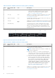
Table 43. AC PSU status indicator codes Power indicator codes Condition Green Indicates that a valid power source is connected to the PSU and the PSU is operational. Blinking amber Indicates an issue with the PSU. Not powered on Indicates that the power is not connected to the PSU. Blinking green Indicates that the firmware of the PSU is being updated. CAUTION: Do not disconnect the power cord or unplug the PSU when updating firmware. If firmware update is interrupted, the PSUs do not function.
Table 44. DC PSU status indicator codes (continued) Power indicator codes Condition Output configuration or conversely, you must power off the system. CAUTION: Combining AC and DC PSUs is not supported. Drive indicator codes The LEDs on the drive carrier indicates the state of each drive. Each drive carrier has two LEDs: an activity LED (green) and a status LED (bicolor, green/amber). The activity LED blinks whenever the drive is accessed. Figure 147. Drive indicators 1. Drive activity LED indicator 2.
Dell Embedded System Diagnostics NOTE: The Dell Embedded System Diagnostics is also known as Enhanced Pre-boot System Assessment (ePSA) diagnostics.
8 Getting help Topics: • • • • Recycling or End-of-Life service information Contacting Dell Accessing system information by using QRL Receiving automated support with SupportAssist Recycling or End-of-Life service information Take back and recycling services are offered for this product in certain countries. If you want to dispose of system components, visit www.dell.com/recyclingworldwide and select the relevant country.
The QRL includes the following information about your system: ● ● ● ● How-to videos Reference materials, including the Installation and Service Manual, LCD diagnostics, and mechanical overview The system service tag to quickly access the specific hardware configuration and warranty information A direct link to Dell to contact technical assistance and sales teams Steps 1. Go to www.dell.com/qrl, and navigate to your specific product or 2.
9 Documentation resources This section provides information about the documentation resources for your system. To view the document that is listed in the documentation resources table: ● From the Dell EMC support site: 1. Click the documentation link that is provided in the Location column in the table. 2. Click the required product or product version. NOTE: To locate the product name and model, see the front of your system. 3. On the Product Support page, click Manuals & documents.
Table 47. Additional documentation resources for your system (continued) Task Document Location For information about earlier versions of the iDRAC documents. www.dell.com/idracmanuals To identify the version of iDRAC available on your system, on the iDRAC web interface, click ?> About. Managing your system For information about installing the operating system, see the operating system documentation. www.dell.