
Owners Manual
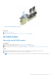
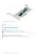
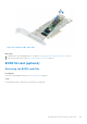
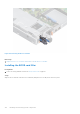
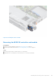
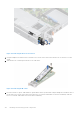
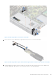
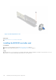
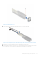
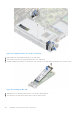
Table Of Contents
- Dell EMC PowerEdge R6525 Installation and Service Manual
- Contents
- About this document
- System overview
- Initial system setup and configuration
- Installing and removing system components
- Safety instructions
- Before working inside your system
- After working inside your system
- Recommended tools
- Cable routing
- RIO card
- Tube clip
- Optional front bezel
- System cover
- Drive backplane cover
- Control panel
- VGA module
- Air shroud
- Cooling fan
- Drives
- Drive backplane
- Rear drive module
- Front PERC module
- System memory
- Processor and heat sink
- Expansion cards and expansion card risers
- Optional serial COM port
- Optional IDSDM module
- MicroSD card
- M.2 SSD module
- BOSS S2 card (optional)
- System battery
- Optional internal USB card
- Intrusion switch module
- Optional OCP card
- Power supply unit
- Trusted Platform Module
- System board
- LOM card and rear I/O board
- Upgrade Kits
- Jumpers and connectors
- System diagnostics and indicator codes
- Getting help
- Documentation resources

Figure 108. Removing the M.2 SSD module
Next steps
1. Replace the M.2 SSD module.
Installing the M.2 SSD module
Prerequisites
1. Follow the safety guidelines listed in the Safety instructions on page 26.
2. Follow the procedure listed in the Before working inside your system on page 27.
3. Remove the BOSS card. Removing BOSS card is similar to removing expansion card from the expansion card riser.
Steps
1. Align the M.2 SSD module at an angle with the BOSS card connector.
2. Insert the M.2 SSD module until it is firmly seated in the BOSS card connector.
3. Using the Phillips #1 screwdriver, secure the M.2 SSD module on the BOSS card with the screw.
122
Installing and removing system components