
Owners Manual
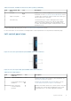
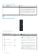
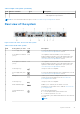
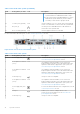
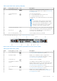
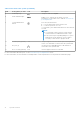
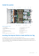
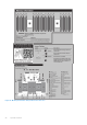
Table Of Contents
- Dell EMC PowerEdge R6525 Installation and Service Manual
- Contents
- About this document
- System overview
- Initial system setup and configuration
- Installing and removing system components
- Safety instructions
- Before working inside your system
- After working inside your system
- Recommended tools
- Cable routing
- RIO card
- Tube clip
- Optional front bezel
- System cover
- Drive backplane cover
- Control panel
- VGA module
- Air shroud
- Cooling fan
- Drives
- Drive backplane
- Rear drive module
- Front PERC module
- System memory
- Processor and heat sink
- Expansion cards and expansion card risers
- Optional serial COM port
- Optional IDSDM module
- MicroSD card
- M.2 SSD module
- BOSS S2 card (optional)
- System battery
- Optional internal USB card
- Intrusion switch module
- Optional OCP card
- Power supply unit
- Trusted Platform Module
- System board
- LOM card and rear I/O board
- Upgrade Kits
- Jumpers and connectors
- System diagnostics and indicator codes
- Getting help
- Documentation resources

Table 5. Right control panel (continued)
Item Indicator or button Icon Description
should not exceed 3 ft (0.91 meters). Quality of the
cable might affect performance.
NOTE: For more information about the ports, see the www.dell.com/poweredgemanuals section.
Rear view of the system
Figure 7. Rear view of the 10 x 2.5-inch drive system
Table 6. Rear view of the system
Item Ports, panels, or slots Icon Description
1 Power supply unit (PSU 1) For more information about the PSU configurations, see the
www.dell.com/poweredgemanuals section.
2
PCIe expansion card riser
(slot 1)
N/A
The expansion card riser enables you to connect PCI
Express expansion cards. For more information about the
expansion cards that are supported on your system, see
www.dell.com/poweredgemanuals section.
3
PCIe expansion card riser
(slot 2)
N/A
The expansion card riser enables you to connect PCI
Express expansion cards. For more information about the
expansion cards that are supported on your system, see
www.dell.com/poweredgemanuals section.
4 USB 2.0 port (1) This port is USB 2.0-compliant.
5 Power supply unit (PSU
2)
For more information about the PSU configurations, see the
www.dell.com/poweredgemanuals section.
6
VGA port Enables you to connect a display device to the
system. For more information, see the www.dell.com/
poweredgemanuals section.
7 USB 3.0 port (1) This port is USB 3.0-compliant.
8 iDRAC dedicated port
Enables you to remotely access iDRAC. For more
information, see the iDRAC User’s Guide at www.dell.com/
poweredgemanuals.
9 System identification
button
Press the system ID button:
● To locate a particular system within a rack.
● To turn the system ID on or off.
To reset iDRAC, press and hold the button for more than 16
seconds.
NOTE:
System overview 13