
Owners Manual
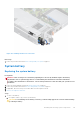
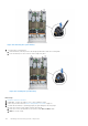
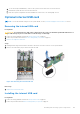
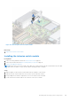
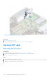
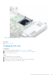
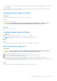
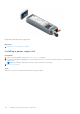
Table Of Contents
- Dell EMC PowerEdge R6525 Installation and Service Manual
- Contents
- About this document
- System overview
- Initial system setup and configuration
- Installing and removing system components
- Safety instructions
- Before working inside your system
- After working inside your system
- Recommended tools
- Cable routing
- RIO card
- Tube clip
- Optional front bezel
- System cover
- Drive backplane cover
- Control panel
- VGA module
- Air shroud
- Cooling fan
- Drives
- Drive backplane
- Rear drive module
- Front PERC module
- System memory
- Processor and heat sink
- Expansion cards and expansion card risers
- Optional serial COM port
- Optional IDSDM module
- MicroSD card
- M.2 SSD module
- BOSS S2 card (optional)
- System battery
- Optional internal USB card
- Intrusion switch module
- Optional OCP card
- Power supply unit
- Trusted Platform Module
- System board
- LOM card and rear I/O board
- Upgrade Kits
- Jumpers and connectors
- System diagnostics and indicator codes
- Getting help
- Documentation resources

Figure 130. Removing a power supply unit
Next steps
1. Replace the PSU or install the PSU blank.
Installing a power supply unit
Prerequisites
1. Follow the safety guidelines listed in the Safety instructions on page 26.
2. For systems that support redundant PSU, ensure that both the PSUs are of the same type and have the same maximum
output power.
NOTE: The maximum output power (shown in watts) is listed on the PSU label.
3. Remove the PSU blank.
Steps
Slide the PSU into the PSU bay until the release latch snaps into place.
140
Installing and removing system components