
Owners Manual
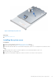
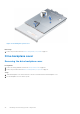
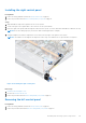
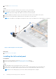
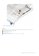
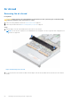
Table Of Contents
- Dell EMC PowerEdge R6525 Installation and Service Manual
- Contents
- About this document
- System overview
- Initial system setup and configuration
- Installing and removing system components
- Safety instructions
- Before working inside your system
- After working inside your system
- Recommended tools
- Cable routing
- RIO card
- Tube clip
- Optional front bezel
- System cover
- Drive backplane cover
- Control panel
- VGA module
- Air shroud
- Cooling fan
- Drives
- Drive backplane
- Rear drive module
- Front PERC module
- System memory
- Processor and heat sink
- Expansion cards and expansion card risers
- Optional serial COM port
- Optional IDSDM module
- MicroSD card
- M.2 SSD module
- BOSS S2 card (optional)
- System battery
- Optional internal USB card
- Intrusion switch module
- Optional OCP card
- Power supply unit
- Trusted Platform Module
- System board
- LOM card and rear I/O board
- Upgrade Kits
- Jumpers and connectors
- System diagnostics and indicator codes
- Getting help
- Documentation resources

Air shroud
Removing the air shroud
Prerequisites
CAUTION: Never operate your system with the air shroud removed. The system may get overheated quickly,
resulting in shutdown of the system and loss of data.
1. Follow the safety guidelines listed in the Safety instructions on page 26.
2. Follow the procedure listed in Before working inside your system on page 27.
Steps
1. Hold the edges of the air shroud, and lift the air shroud out of the system.
NOTE: The air shroud is required for the standard heat sink configuration. For the L-type heat sink configuration, air
shroud is not supported.
Figure 45. Removing the air shroud
2. For the air shroud on the rear drive module, hold the edges of the air shroud, and lift the air shroud out of the rear drive
module.
50
Installing and removing system components