
Owners Manual
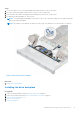
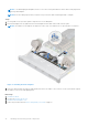
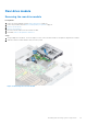
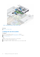
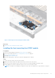
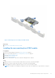
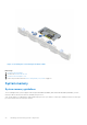
Table Of Contents
- Dell EMC PowerEdge R6525 Installation and Service Manual
- Contents
- About this document
- System overview
- Initial system setup and configuration
- Installing and removing system components
- Safety instructions
- Before working inside your system
- After working inside your system
- Recommended tools
- Cable routing
- RIO card
- Tube clip
- Optional front bezel
- System cover
- Drive backplane cover
- Control panel
- VGA module
- Air shroud
- Cooling fan
- Drives
- Drive backplane
- Rear drive module
- Front PERC module
- System memory
- Processor and heat sink
- Expansion cards and expansion card risers
- Optional serial COM port
- Optional IDSDM module
- MicroSD card
- M.2 SSD module
- BOSS S2 card (optional)
- System battery
- Optional internal USB card
- Intrusion switch module
- Optional OCP card
- Power supply unit
- Trusted Platform Module
- System board
- LOM card and rear I/O board
- Upgrade Kits
- Jumpers and connectors
- System diagnostics and indicator codes
- Getting help
- Documentation resources

Figure 69. Installing the rear mounting front PERC module
Next steps
1. Install the drive backplane.
2. If removed, install the air shroud.
3. Install the drive backplane cover.
4. Follow the procedure listed in After working inside your system on page 27.
System memory
System memory guidelines
The PowerEdge R6525 system supports DDR4 registered DIMMs (RDIMMs) and Load Reduced DIMM (LRDIMMs). System
memory holds the instructions that are started by the processor.
Your system memory is organized into eight channels per processor (two memory sockets per channel),16 memory sockets per
processor and 32 memory sockets per system.
70
Installing and removing system components