
Owners Manual


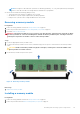
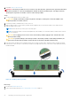
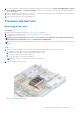
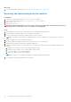
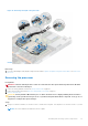
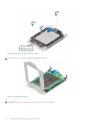
Table Of Contents
- Dell EMC PowerEdge R6525 Installation and Service Manual
- Contents
- About this document
- System overview
- Initial system setup and configuration
- Installing and removing system components
- Safety instructions
- Before working inside your system
- After working inside your system
- Recommended tools
- Cable routing
- RIO card
- Tube clip
- Optional front bezel
- System cover
- Drive backplane cover
- Control panel
- VGA module
- Air shroud
- Cooling fan
- Drives
- Drive backplane
- Rear drive module
- Front PERC module
- System memory
- Processor and heat sink
- Expansion cards and expansion card risers
- Optional serial COM port
- Optional IDSDM module
- MicroSD card
- M.2 SSD module
- BOSS S2 card (optional)
- System battery
- Optional internal USB card
- Intrusion switch module
- Optional OCP card
- Power supply unit
- Trusted Platform Module
- System board
- LOM card and rear I/O board
- Upgrade Kits
- Jumpers and connectors
- System diagnostics and indicator codes
- Getting help
- Documentation resources

3. If installed, remove the air shroud.
WARNING: The memory modules are hot to touch for some time after the system has been powered down. Allow
the memory modules to cool before handling them. Handle the memory modules by the card edges and avoid
touching the components or metallic contacts on the memory module.
Steps
1. Locate the appropriate memory module socket.
CAUTION: Handle each memory module only by the card edges, ensuring not to touch the middle of the
memory module or metallic contacts.
2. If a memory module is installed in the socket, remove it.
3. Align the edge connector of the memory module with the alignment key of the memory module socket, and insert the
memory module in the socket.
NOTE: Ensure the memory socket ejectors are fully open.
NOTE: The memory module socket has an alignment key that enables you to install the memory module in the socket in
only one orientation.
CAUTION: Do not apply pressure at the center of the memory module; apply pressure at both ends of the
memory module evenly.
CAUTION: To prevent damage to the memory module or the memory module socket during installation, do
not bend or flex the memory module; insert both ends of the memory module simultaneously.
4. Press the memory module with your thumbs until the ejectors firmly click into place. When the memory module is properly
seated in the socket, the levers on the memory module socket align with the levers on the other sockets that have memory
modules installed.
Figure 72. Installing a memory module
Next steps
1. If removed, install the air shroud.
2. Follow the procedure listed in After working inside your system on page 27.
76
Installing and removing system components