
Owners Manual
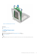
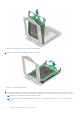
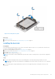
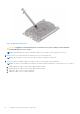
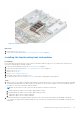
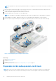
Table Of Contents
- Dell EMC PowerEdge R6525 Installation and Service Manual
- Contents
- About this document
- System overview
- Initial system setup and configuration
- Installing and removing system components
- Safety instructions
- Before working inside your system
- After working inside your system
- Recommended tools
- Cable routing
- RIO card
- Tube clip
- Optional front bezel
- System cover
- Drive backplane cover
- Control panel
- VGA module
- Air shroud
- Cooling fan
- Drives
- Drive backplane
- Rear drive module
- Front PERC module
- System memory
- Processor and heat sink
- Expansion cards and expansion card risers
- Optional serial COM port
- Optional IDSDM module
- MicroSD card
- M.2 SSD module
- BOSS S2 card (optional)
- System battery
- Optional internal USB card
- Intrusion switch module
- Optional OCP card
- Power supply unit
- Trusted Platform Module
- System board
- LOM card and rear I/O board
- Upgrade Kits
- Jumpers and connectors
- System diagnostics and indicator codes
- Getting help
- Documentation resources

Figure 82. Installing a heat sink
Next steps
1. If removed, install the air shroud.
2. Follow the procedure listed in the After working inside your system on page 27.
Installing the liquid cooling heat sink modules
Prerequisites
Never uninstall the heat sink from a processor unless you intend to replace the processor or system board. The heat sink is
necessary to maintain proper thermal conditions.
1. Follow the safety guidelines listed in the Safety instructions on page 26.
2. Follow the procedure listed in the Before working inside your system on page 27.
3. Remove the system cover.
4. Remove the air shroud.
5. Remove riser 3 or liquid cooling riser 3.
6. If installed, remove the processor dust cover.
7. For new heat sinks, refer to Installing the heat sink step 1 and 2 for applying the thermal grease.
Steps
1. Align the screws on the liquid cooling heat sink modules with the standoff screws on the system board. Ensure that the liquid
cooling tubes and liquid detection cable are placed towards the rear of the chassis. Using a Torx #T20 screwdriver, tighten
the captive screws in the order that is mentioned below:
NOTE: The A1 extrusion on the L-type heat sink should face towards the system side.
a. Partially tighten the captive screws 1 and 2 (approximately 3 turns).
b. Partially tighten the captive screws 3 and 4 (approximately 3 turns).
c. Tighten the captive screws 1 and 2 completely.
d. Tighten the captive screws 3 and 4 completely.
2. Ensure that the liquid cooling tubes leading towards the front of the chassis is placed between the DIMM slots and the
J_SL connectors. And the tubes leading towards the rear of the chassis are placed in between the DIMM slots and the relay
components.
Installing and removing system components
85