
Users Guide
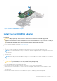
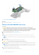

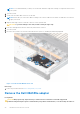
Table Of Contents
- Dell Technologies Host Bus Adapter User's Guide HBA355i and HBA355e
- Dell HBA355i and Dell HBA355e
- Dell HBA355i
- Dell HBA355i front card
- Dell HBA355e
- Dell HBA355i and Dell HBA355e technical specifications
- PowerEdge systems supported by Dell HBA355i
- PowerEdge systems supported by Dell HBA355e
- Operating systems supported by Dell HBA355i and Dell HBA355e
- MD1400 and MD1420 enclosure support for Dell HBA355e
- Port support matrix for dual path on the same MD1400 and MD1420 enclosure
- ME484 enclosure support for Dell HBA355e
- Port support matrix for dual path on the same ME484 enclosure
- Tape drive support for Dell HBA355e
- Applications supported by Dell HBA355i and Dell HBA355e
- Dell HBA355e enclosure support
- Features of Dell HBA355i and Dell HBA355e
- Installation and removal of cards
- Safety instructions
- Before working inside your system
- After working inside your system
- Remove the Dell HBA355i adapter
- Install the Dell HBA355i adapter
- Remove the Dell HBA355i front card
- Install the Dell HBA355i front card
- Remove the Dell HBA355e adapter
- Install the Dell HBA355e adapter
- Connect Dell HBA355e to the storage enclosure
- Driver support Dell HBA355i and Dell HBA355e
- Manage Dell HBA355i and Dell HBA355e cards using HII configuration utility
- Updating the firmware of Dell HBA355i and Dell HBA355e
- Getting help
- Troubleshooting
- Known issues
- VendorID and ProductID for tape drives
- System reserved partition after Windows installation
- Device settings in HII shows PCIe slot information
- Intermittent RSODs appears when a faulty drive is connected to HBA
- Selecting drive for operating system installation in legacy mode
- Adapter configuration change message
- Incompatible firmware image when incorrect payload is used
- Additional disks displayed in the command line interface
- Known issues
- Documentation resources

Figure 4. Remove the Dell HBA355i adapter
Install the Dell HBA355i adapter
Prerequisites
CAUTION:
Many repairs may only be done by a certified service technician. You should only perform
troubleshooting and simple repairs as authorized in your product documentation, or as directed by the online or
telephone service and support team. Damage due to servicing that is not authorized by Dell is not covered by
your warranty. Read and follow the safety instructions that are shipped with your product.
1. Follow the safety guidelines listed in the Safety instructions.
2. Follow the procedure listed in the Before working inside your system.
Steps
1. Turn off the system, including any attached peripherals, and disconnect the system from the electrical outlet.
NOTE:
It is recommended that you always use a static mat and static strap while working on components in the interior
of the system.
2. Open the system.
3. Connect the SAS data cable connectors to the card.
NOTE:
Ensure that you connect the cable according to the connector labels on the cable. The cable does not function
properly if reversed.
4. Align the card-edge connector with the connector on the system board.
CAUTION: To prevent damage to the card, hold the card by its edges only.
5. Press the card-edge down until the card is fully seated.
6. Route the SAS data cable through the channel on the inner side of the chassis to the backplane.
7. Attach the connector labeled SAS A to connector SAS A on the backplane, and attach the connector labeled SAS B to
connector SAS B on the backplane.
8. Close the system.
9. Reconnect the system to its electrical outlet and turn the system on, including any attached peripherals.
Installation and removal of cards
17