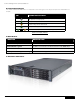
Dell ™ POWEREDGE R710 ™ technical guidebook Inside the poweredge R710
Dell™ PowerEdge™ R710 Technical Guidebook TABLE OF CONTENTS Section 1. system overview A. Overview / Description B. Product Features Summary 6 6 6 Section 2. Mechanical A. Chassis Description B. Dimensions and Weight C. Front Panel View and Features D. Back Panel View and Features E. Power Supply Indicators F. NIC Indicators G. Side Views and Features H. Rails and Cable Management I. Fans J. Control Panel / LCD K. Security I. Cover Latch II. Bezel III. Hard Drive IV. TPM V. Power Off Security VI.
Dell™ PowerEdge™ R710 Technical Guidebook Section 5. Block Diagram 19 Section 6. Processors A. Overview / Description B. Features C. Supported Processors D. Processor Configurations 21 21 21 21 22 Section 7. Memory A. Overview / Description B. DIMMs Supported C. Speed D. Slots / Risers E. Supported Configurations F. Mirroring G. Advanced ECC (Lockstep) Modes H. Optimizer (Independent Channel) Mode 23 23 23 24 27 27 28 28 28 Section 8. Chipset A. Overview / Description 29 29 Section 9. BIOS A.
Dell™ PowerEdge™ R710 Technical Guidebook D. Storage Controllers I. SAS 6/iR II. PERC 6i E. LED Indicators F. Optical Drives G. Tape Drives 39 39 40 41 41 41 Section 13. Video A. Overview / Description 42 42 Section 14. Audio A. Overview / Description 43 43 Section 15. Rack Information A. Overview / Description B. Cable Management Arm (CMA) C. Rails 43 43 43 44 Section 16. Operating Systems A. Overview / Description 45 45 Section 17. Virtualization A. Overview / Description 47 47 Section 18.
Dell™ PowerEdge™ R710 Technical Guidebook The Dell™ PowerEdge™ R710 The Dell PowerEdge R710 is designed to be the cornerstone of today’s competitive enterprise. Engineered in response to input from IT professionals, it is the next-generation 2U rack server created to efficiently address a wide range of key business applications.
Dell™ PowerEdge™ R710 Technical Guidebook strategic technology usage. Secure, efficient, and more user friendly than its predecessors, the Dell Unified Server Configurator (USC) delivers “Instant On” integrated manageability through a single access point. You get quick, persistent access to the tool because it is embedded and integrated into the system for increased flexibility and capabilities.
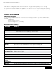
Dell™ PowerEdge™ R710 Technical Guidebook Feature Details RAID PERC 6i utilizing battery backed 256MB DDRII 667 NIC/LOM Broadcom 5809C (2 cards/4ports) USB Five (two front, two rear, one internal) Power Supplies Two hot-plug high-efficient 570W PSU OR Two hot-plug 870W PSUs (1+1) Front Control Panel The system control panel is located on the front of the system chassis to provide user access to buttons, display, and I/O interfaces System ID Front and rear (0x0235) Fans Five hot-swappable Add
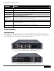
Dell™ PowerEdge™ R710 Technical Guidebook B. Dimensions and Weight Height 8.64cm (3.40") Width 44.31cm (17.44") Depth 68.07cm (26.80") Weight (maximum config) 26.1kg (57.54lbs) . C. Front Panel View and Features Front I/O panel access including USB and VGA interfaces. The following components are located on the front: • Express service tag (Information tag). A slide-out panel for system identification labels • Power on indicator, power button • NMI indicator (Nonmaskable interrupt).
Dell™ PowerEdge™ R710 Technical Guidebook E. Power Supply Indicators The PSUs on the PE R710 have one status bi-color LED: green for AC power present and amber for a fault. led Power Supply status AC power is not present AC power is present Fault of any kind is detected DC power is applied to the system PSU mismatch (when hot-added/swapped) Table: Power Supply Indicator F.
Dell™ PowerEdge™ R710 Technical Guidebook H. Rails and Cable Management Rack installation components such as rails are provided with the PowerEdge R710 Rack Kit. The rack installation components are as follows: Sliding rack mount with latest generation Cable Management Arm (CMA). When the system is installed in a rack, please observe the following guideline: hen the system is installed in a rack, only Dell-approved CMAs should be installed behind W the chassis.
Dell™ PowerEdge™ R710 Technical Guidebook J. Control Panel / LCD The control panel board is connected to the planar via a 60-wire ribbon cable and a separate 5-wire cable for USB signals only. The LCD plugs into the control panel through a 20-pin ZIF connector and flex cable. The system control panel is located on the front of the system chassis to provide user access to switches, display, and I/O interfaces.
Dell™ PowerEdge™ R710 Technical Guidebook II. Bezel A metal bezel is mounted to the chassis front to provide the Dell ID. A lock on the bezel is used to protect un-authorized access to system peripherals and the control panel. System status via the LCD is viewable even when the bezel is installed. III. Hard Drive The optional front bezel of the system contains a lock. A locked bezel secures the system hard drives. IV.
Dell™ PowerEdge™ R710 Technical Guidebook Section 3. Electrical A. Volatility See Appendix A of this Technical Guidebook B. ePPID (Electronic Piece Part Identification) ePPID is an electronic repository for information from the PPID label that is stored in non-volatile RAM. The BIOS reports the ePPID information using SMBIOS data structures.
Dell™ PowerEdge™ R710 Technical Guidebook Section 4. Power, Thermal, Acoustic A. Power Efficiencies One of the main features of the 11th generation of PowerEdge servers is enhanced power efficiency.
Dell™ PowerEdge™ R710 Technical Guidebook C. Power Supply Specifications AC Power supply (per power supply) Wattage 870 Watt (High Output) 570 Watt (Energy Smart) Voltage 90-264 VAC, autoranging, 47-63Hz Heat Dissipation 2968.6 BTU/hr maximum (High Output) 1944.9 BTU/hr maximum (Energy Smart) Maximum Inrush Current Under typical line conditions and over the entire system ambient operating range, the inrush current may reach 55A per power supply for 10ms or less.
Dell™ PowerEdge™ R710 Technical Guidebook D. Environmental Specifications temperature Operating 10° to 35°C (50° to 95°F) with a maximum temperature gradation of 10°C per hour. Note: For altitudes above 2950 feet, the maximum operating temperature is derated 1°F/550 ft.
Dell™ PowerEdge™ R710 Technical Guidebook E. Power Consumption Testing Feature 1 Energy Smart PSU High Output PSU Dimensions L-206.4 mm1 x W-67.5 mm x H-76.
Dell™ PowerEdge™ R710 Technical Guidebook H. Acoustics The acoustical design of the PowerEdge R710 reflects the following: • Adherence to Dell’s high sound quality standards. Sound quality is different from sound power level and sound pressure level in that it describes how humans respond to annoyances in sound, like whistles, hums, etc. One of the sound quality metrics in the Dell specification is prominence ratio of a tone, and this is listed in the table below. • Office environment acoustics.
Dell™ PowerEdge™ R710 Technical Guidebook Section 5.
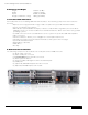
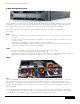
Dell™ PowerEdge™ R710 Technical Guidebook 1 2 3 4 5 6 7 8 8 9 11 10 1. Embedded Network Interface Ports (4) 2. PCIe Gen2 Riser / Slots 3. Broadcom 5709c Network Interface Chip 4. PCIe Gen2 Riser / Slots 5. iDRAC6 Enterprise (Optional) 6. iDRAC6 Express / Lifecycle Controller 7. Heat Sink / Processor Socket 8. DIMM Slots 9. Hot plug, redundant fans 10. Hard drive bay, 6" x 3.5" 11.
Dell™ PowerEdge™ R710 Technical Guidebook Section 6. Processors A. Overview / Description The Intel 5500 series 2S processor (Nehalem - Efficient Processor (EP)), is the microprocessor designed specifically for servers and workstation applications. The processor features quad-core processing to maximize performance and performance/watt for data center infrastructures and highly dense deployments.
Dell™ PowerEdge™ R710 Technical Guidebook model speed power cache cores E5530 2.40GHz 80W 8M 4 E5520 2.26GHz 80W 8M 4 L5520 2.26GHz 60W 8M 4 E5506 2.13GHz 80W 4M 4 L5506 2.13GHz 60W 4M 4 E5504 2.00GHz 80W 4M 4 E5502 1.86GHz 80W 4M 2 D.
Dell™ PowerEdge™ R710 Technical Guidebook CPU Power Voltage Regulation Modules (EVRD 11.1) Voltage regulation to the 5500 series 2S processor (Nehalem EP) is provided by EVRD (Enterprise Voltage Regulator-Down). EVRDs are embedded on the planar. CPU core voltage is not shared between processors. EVRDs support static phase shedding and power management via the PMBus. Section 7. Memory A.
Dell™ PowerEdge™ R710 Technical Guidebook • One channel per CPU populated: • This is a simple Memory Optimized mode. Mirroring is not supported. The PowerEdge R710 memory interface supports memory demand and patrol scrubbing, single-bit correction and multi-bit error detection. Correction of a x4 or x8 device failure is also possible with SDDC in the Advanced ECC mode. Additionally, correction of a x4 device failure is possible in the Memory Optimized mode.
Dell™ PowerEdge™ R710 Technical Guidebook The table below shows the memory populations and the maximum frequency achievable for that configuration. dimm type UDIMM RDIMM DImm 0 dimm 1 dimm 2 # of dimms SR 1 DR 1 SR SR 2 SR DR 2 DR DR 2 SR 1 DR 1 QR 1 SR SR 2 SR DR 2 DR DR 2 QR SR 2 QR DR 2 QR QR 2 SR SR SR 3 SR SR DR 3 SR DR DR 3 DR DR DR 3 800 1066 1333 Note: For QR mixed with an SR/DR DIMM, the QR needs to be in the white DIMM connector.
Dell™ PowerEdge™ R710 Technical Guidebook NHM-EP Platform Memory Overview •P latform capability (18 DIMMs): – Up to 3 channels per CPU – Up to 3 DIMMS per channel 1 •M emory Types Supported: – DDR 1333, 1066, and 800 – Registered (RDIMM) and unbuffered (UDIMM) – Single-rank (SR), dual-rank (DR), quad-rank (QR) Up to 3 channels per CPU 2 NHM-EP NHM-EP 3 1 2 3 Up to 3 DIMMs per Channel • System memory Speed (i.e.
Dell™ PowerEdge™ R710 Technical Guidebook D. Slots / Risers The PowerEdge R710 has 18 DIMM slots for memory. It does not have any riser cards for DIMM population. E.
Dell™ PowerEdge™ R710 Technical Guidebook memory mode memory sockets UDIMM memory module size 1 2 4 single processor 3 5 6 x x x x x x x x x x OPTIMIZER 1GB Advanced ECCa 2GB Mirroring memory mode 1GB RDIMM Memory Module 2GB Size 1GB 2GB physical memory (GB) dual processor available memory (GB) 1 x x x x x x x x x x x x x x x x x x x x x x None x x memory sockets x x x x 1 2 3 None x x 4 x None x x None 5 x 6 x x x x x x x x x x x x 2 3 4 6 2 4 6 8 12 physical
Dell™ PowerEdge™ R710 Technical Guidebook Section 8. Chipset A. Overview / Description The PowerEdge R710 planar incorporated the Intel 5520 chipset (code named Tylersburg) for I/O and processor interfacing. Tylersburg is designed to support Intel's 5500 series processors (code named Nehalem-EP), QPI interconnect, DDR3 memory technology, and PCI Express Generation 2. The Tylersburg chipset consists of the Tylersburg-36D IOH and ICH9.
Dell™ PowerEdge™ R710 Technical Guidebook Intel Direct Media Interface (DMI) The DMI (previously called the Enterprise Southbridge Interface) connects the Tylersburg IOH with the Intel I/O Controller Hub (ICH). The DMI is equivalent to a x4 PCIe Gen1 link with a transfer rate of 1 Gb/s in each direction. PCI Express Generation 2 PCI Express is a serial point-to-point interconnect for I/O devices. PCIe Gen2 doubles the signaling bit rate of each lane from 2.5 Gb/s to 5 Gb/s.
Dell™ PowerEdge™ R710 Technical Guidebook Section 9. BIOS A. Overview / Description The PowerEdge R710 BIOS is based on the Dell BIOS core, and supports the following features: • Nehalem-EP 2S Support • Simultaneous Multi-Threading (SMT) support • CPU Turbo Mode support • PCI 2.3 compliant • Plug n’ Play 1.0a compliant • MP (Multiprocessor) 1.
Dell™ PowerEdge™ R710 Technical Guidebook proc number qdF # frequency standard tdp lfm tdp p-state notes E5540 Q1G2 2.53 80 75 Pmin+7 D-0 X5550 Q1GJ 2.67 95 75 Pmin+8 D-0 X5560 Q1GF 2.80 95 75 Pmin+9 D-0 X5570 Q1G9 2.93 95 75 Pmin+10 D-0 W5580 Q1G6 3.20 130 98 Pmin+12 D-0 Table: Nehalem P-State Projections C. I2C (Inter-Integrated Circuit) What is I2C? A simple bi-directional 2-wire bus for efficient inter-integrated circuit control.
Dell™ PowerEdge™ R710 Technical Guidebook Section 11. I/O Slots A. Overview / Description The PowerEdge R710 requires two PCI Express risers: Riser 1 and Riser 2. Each riser connects to the planar through an x16 PCI Express connector. • Riser 1 consists of two x4 slots and a third x4 slot dedicated for internal SAS storage through the PERC 6i or SAS 6/iR. • The default Riser 2 consists of two x8 PCI Express connectors. • There is also an optional x16 Riser 2 that supports one x16 PCI Express card.
Dell™ PowerEdge™ R710 Technical Guidebook Poweredge R710 PCI Express Gen2 Slots Slot 1: Half-Length (6.6" Factory Installation) / Full-Height (x8 connector), x4 link width Slot 2: Full-Length (12.2" Factory Installation) / Full-Height (x8 connector), x8 link width Slot 3: Full-Length (12.2" Factory Installation) / Full-Height (x8 connector), x8 link width Slot 4: Half-Length (6.6" Factory Installation) / Full-Height (x8 connector), x4 link width Slot 5: Half-Length (6.
Dell™ PowerEdge™ R710 Technical Guidebook B. PCI Express Risers The two PowerEdge R710 PCI Express risers provide up to four expansion slots and one internal slot as follows: • Two x8 and two x4 PCI Express Gen2 slots, connected to the IOH • One x4 PCI Express Gen1 slot for internal storage, connected to the IOH • Support for three full-height 9.
Dell™ PowerEdge™ R710 Technical Guidebook Section 12. Storage A. Overview / Description The PowerEdge R710 supports three different backplanes to support different hard drive configurations: six 3.5" hard drives, four 3.5" hard drives, or eight 2.5" hard drives. On each backplane are two LED indicators per drive slot with one or two mini-SAS x4 cable connectors for connecting the backplane to the integrated SAS 6/iR or PERC 6i, and a power connector to connect to the planar.
Dell™ PowerEdge™ R710 Technical Guidebook For mixed SAS/SATA configurations, SAS drives must be installed as a pair in drive slots 0 and 1. One mixed 2.5" and 3.5" hard drive configuration is allowed: a pair of 2.5" 10k rpm SAS drives can be installed with an adapter in a 3.5" hard drive carrier in drive slots 0 and 1. The remaining hard drives must be 3.5" hard drives and must be either all SAS or all SATA. PowerEdge R710 Platforms 4 All 2.5" HDD SAS (or) SATA 4 All 2.
Dell™ PowerEdge™ R710 Technical Guidebook IV. Diskless Configuration Support The system supports diskless configuration with no storage controller (SAS 6/iR or PERC 6i) installed in the system. A 2.5" HDD backplane is still installed in this configuration. V. Hard Drive LED Indicators Each disk drive carrier has two LED indicators visible from the front of the system. One is a green LED for disk activity and the other is a bicolor (green/amber) LED for status information.
Dell™ PowerEdge™ R710 Technical Guidebook config type configs Min HDD 9 SAS/SATA (RAID) config type SSD (RAID) SSD/SAS (RAID) description non-mixed drives, all sata or all sas Integrated SAS/SATA RAID MSSR1R1- X 1/RAID 1 (SAS 6/iR, PERC 6/i) configs 10 MSSR1R5-X Integrated description SAS/SATA RAID 1/RAID 5 (PERC 6/i) Max HDD non-mixed drives, all SSD Min HDD Max HDD Mixed SAS/ SATA Min 2xSAS+1xSATA 2.5": Max 2xSAS + 6xSATA 3.5": Max 2xSAS + 6xSATA Min HDD MAX HDD 2.5"=2+2 2.5"=2+2 3.
Dell™ PowerEdge™ R710 Technical Guidebook II. PERC 6i For customers who want a hardware RAID solution, the PERC 6i is an option. The PERC 6i uses the LSI 1078 ROC (RAID on Chip) processor with a PCI Express host interface and DDR2 memory. A battery is also available for backup.
Dell™ PowerEdge™ R710 Technical Guidebook E. LED Indicators Each disk drive carrier has two LED indicators visible from the front of the system. One is a green LED for disk activity and the other is a bicolor (green/amber) LED for status information. The activity LED is driven by the disk drive during normal operation. The bicolor LED is controlled by the SEP device on the backplane. Both LEDs are used to indicate certain conditions under direction of a storage controller. F.
Dell™ PowerEdge™ R710 Technical Guidebook chassis config tape backup unit (internal) Backplane Type Config 3.5" x 6" 3.5" x 4" 2.5" x 8 TBU Controller TBU Cable No TBU N/A N/A No TBU N/A N/A Internal for 3.5 Bay (RD 1000 Half-Height SATA) Connects to MB XR724 DAT72 for 3.5 Bay (Half-Height SCSI) LSI 2032 (SCSI) HBA DR017 No TBU N/A N/A Internal for 3.5 Bay (RD 1000 Half-Height SATA) Connects to MB RN694 DAT72 for 3.5 Bay (Half-Height SCSI) LSI 2032 (SCSI) HBA CJ176 Section 13.
Dell™ PowerEdge™ R710 Technical Guidebook Section 14. Audio A. Overview / Description No speakers supported Section 15. Rack Information A. Overview / Description Rack installation components such as rails are provided with the PowerEdge R710 Rack Kit. The rack installation components are as follows: Sliding Rack mount with latest generation Cable Management Arm (CMA).
Dell™ PowerEdge™ R710 Technical Guidebook C.
Dell™ PowerEdge™ R710 Technical Guidebook Section 16. Operating Systems A. Overview / Description The PowerEdge R710 supports Windows®, Linux®, and Solaris™ Operating Systems.
Dell™ PowerEdge™ R710 Technical Guidebook x86 or x64 INSTALLATION Factory INSTALLATION logo certification schedule Test/ Validate support Yes Windows Hardware Quality Labs Windows 2008 Release 2 Available in November 2009 January 2010 Yes Yes Available in June 2009 n/A Available in June 2009 Yes Yes Yes n/A Shipping Yes Yes Available in June 2009 n/A Available in June 2009 Yes Yes n/A Shipping Yes Yes Available in June 2009 n/A Available in June 2009 Yes Yes Drop in the
Dell™ PowerEdge™ R710 Technical Guidebook Section 17. Virtualization A. Overview / Description Supported embedded hypervisors: • Microsoft® Windows Server® 2008 Hyper-V • VMware® ESXi Version 4.0 and 3.5 update 4 • Citrix® XenServer 5.0 with Hotfix 1 or later Section 18. Systems Management A. Overview / Description Dell is focused on delivering open, flexible, and integrated solutions the help our customers reduce the complexity of managing disparate IT assets.
Dell™ PowerEdge™ R710 Technical Guidebook Dell Management Console DVD: The Dell Management Console is a Web-based systems management software that enables you to discover and inventory devices on your network. It also provides advanced functions, such as health and performance monitoring of networked devices and patch management capabilities for Dell systems.
Dell™ PowerEdge™ R710 Technical Guidebook feature description Faster O/S Installation Drivers and the installation utility are embedded on system, so no need to scour DELL.
Dell™ PowerEdge™ R710 Technical Guidebook A more detailed feature list for iDRAC6 Enterprise and vFlash is included in the table below. BMC iDRAC6 Express iDRAC6 Enterprise VFlash Media 4 4 4 4 Web-based GUI 4 4 4 SNMP 4 4 4 WSMAN 4 4 4 SMASH-CLP 4 4 4 4 4 Feature Interface and Standards Support IPMI 2.
Dell™ PowerEdge™ R710 Technical Guidebook Feature BMC iDRAC6 Express Virtual console sharing iDRAC6 Enterprise VFlash Media 4 4 Virtual flash 4 Monitoring Sensor Monitoring and Alerting 4 4 4 4 Real-time Power Monitoring 4 4 4 Real-time Power Graphing 4 4 4 Historical Power Counters 4 4 4 4 4 4 RAC Log 4 4 4 Trace Log 4 4 4 Logging Features System Event Log 4 51
Dell™ PowerEdge™ R710 Technical Guidebook Section 19. Peripherals A. USB peripherals The PowerEdge R710 supports the following USB devices: • DVD (bootable; requires two USB ports) • USB Key (bootable) • Keyboard (only one USB keyboard is supported) • Mouse (only one USB mouse is supported) B. External Storage external storage EMC's AX Arrays (SCSI, FC, and iSCSI) SAN Support EMC's CX Arrays (SCSI, FC, and iSCSI) EqualLogic's PS5XXX Arrays (iSCSI) OMSS X.
Dell™ PowerEdge™ R710 Technical Guidebook Section 20. Documentation A. Overview, Description, and List PowerEdge R710 and other 11G systems use the new enterprise documentation set. The following is a summary of some of the documents slated for the PowerEdge R710 product. For the complete list of documents, including language requirements and delivery scheduling, refer to the Documentation Matrix and the Documentation Milestones in the InfoDev Functional Publications Plan.
Dell™ PowerEdge™ R710 Technical Guidebook Appendix R710 Volatility Chart. NonVolatile RAM volatile ram Reference designator QTY Size Type [e.g.
Dell™ PowerEdge™ R710 Technical Guidebook R710 Volatility Chart Continued. Can user programs or operating system write data to it during normal operation? Purpose? [e.g.
Dell™ PowerEdge™ R710 Technical Guidebook R710 Volatility Chart Continued.
Dell™ PowerEdge™ R710 Technical Guidebook R710 Volatility Chart Continued. How is data input to this memory? Planar, Poweredge R710 Controller Configuration Data FRU Integrated Mirroring NVSRAM iDRAC6 Enterprise VFlash Loading flash memory requires a vendor-provided firmware file and loader program that is executed by booting up the system from a floppy or OS-based executable (DUPs, Unified Server Configurator) containing the firmware file and the loader.
Dell™ PowerEdge™ R710 Technical Guidebook R710 Volatility Chart Continued. How is this memory write protected? How is the memory cleared? Planar, Poweredge R710 PERC 6/i Integrated PERC NVSRAM Config Data PERC Firmware Storage controller firmware accessed only N/A - not in-system clearable Write control access by storage controller firmware PERC Cache RAM Storage controller firmware accessed only N/A - not in-system clearable Storage controller firmware clearable only.