
White Paper

Cable Routing Procedures for Dell™ PowerEdge™ R310 & R410 Systems
Page 1
Contents
Introduction ........................................................................................................................................................... 2
Section 1: Cabling a Dell™ PowerEdge™ R310 or R410 With a Cable Management Arm (CMA) .......... 2
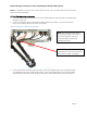
1.1 Connecting the CMA Cables to the System ....................................................................................... 2
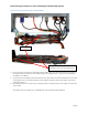
1.2 Installing the Inner CMA Attachment Bracket .................................................................................... 3
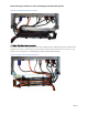
1.3 Routing the Power Cables Through the Strain Reliefs ...................................................................... 3
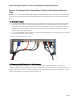
1.4 Routing the Cables Through the CMA ................................................................................................. 3
1.5 Left-Side Mounting Instructions ........................................................................................................... 4
1.6 Right-Side Mounting Instructions ......................................................................................................... 6
Section 2: Cabling a Dell™ PowerEdge™ R310 or R410 System Without a CMA ...................................... 7
2.1 Routing the Cables ................................................................................................................................... 7
2.2 Removing the CMA Brackets for Shallow Racks ................................................................................. 7
Section 3: Replacing a Power Supply on a PowerEdge™ R310 or R410 System With a CMA ................ 8
Section 4: Cabling a PowerEdge™ R310 or R410 System Installed in Static Rails .................................... 9
Table of Figures
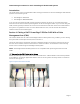
Figure 1: System with Cables Installed
................................................................................................................... 2
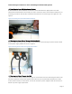
Figure 2: Attaching the Inner CMA Attachment Bracket
..................................................................................... 3
Figure 3: Routing Power Cables Through the Strain Reliefs
.............................................................................. 3
Figure 4: Routing the Cables Through the CMA
.................................................................................................. 4
Figure 5: Attaching the KVM Dongle to the CMA Basket
.................................................................................... 5
Figure 6: Left-Side Mounted CMA Installation
...................................................................................................... 6
Figure 7: Right-Side Mounted CMA Installation
................................................................................................... 6
Figure 8: Cable Routing Without a CMA
................................................................................................................ 7
Figure 9: Removing the CMA Brackets for Shallow Racks
.................................................................................. 8
Figure 10: Disconnecting the Inner CMA Attachment Bracket
.......................................................................... 9
Figure 11: Replacing the Outer Power Supply
...................................................................................................... 9
Figure 12: Cabling a System Installed in Static Rails
.......................................................................................... 10