Dell Energy Smart Rack Enclosure Installation Guide Guide d'installation Installationsanleitung 設置ガイド Guía de instalación
Dell Energy Smart Rack Enclosure Installation Guide
Notes, Cautions, and Warnings NOTE: A NOTE indicates important information that helps you make better use of your computer. CAUTION: A CAUTION indicates potential damage to hardware or loss of data if instructions are not followed. WARNING: A WARNING indicates a potential for property damage, personal injury, or death. ____________________ Information in this publication is subject to change without notice. © 2011 Dell Inc. All rights reserved.
Contents Safety Instructions . . . . . . . . . . . . . . . . . . . . . SAFETY: Rack Mounting of Systems . . . . . . . . . 5 . . . . . . . . . . . . . . 6 . . . . . . . . . . . . . . . . . 6 . . . . . . . . . . . . . . . . . . 7 Rack Installation Instructions . Rack Specifications Before You Begin . 5 . . . . . . . . . 8 . . . . . . . . . . . . . . . 8 Recommended Tools and Supplies . Installing Rack Cabinets Opening and Closing the Front Rack Door . . . . . .
4 Contents
Safety Instructions Use the following safety guidelines to ensure your own personal safety and to protect your equipment and working environment from potential damage. For complete safety and regulatory information, see the safety instructions that shipped with your equipment. Warranty information may be included in this document or as a separate document. SAFETY: Rack Mounting of Systems Observe the following precautions for rack stability and safety.
• The air channel located at the bottom of the rack is used to direct cool air from the floor to the front of the rack enclosure. The air channel must always remain at the bottom of the rack (in 1U and 2U) and must not be moved to a different location in the rack. • Do not use the air channel as a step or as a shelf to support components.
Before You Begin WARNING: Before you begin installing your rack, carefully read "Important Safety Information" on page 7 and the safety instructions that came with the rack. WARNING: When installing multiple systems in a rack, complete all the procedures for the current system before attempting to install the next system. WARNING: Rack cabinets can be extremely heavy and can move easily on the casters. The cabinet has no brakes. Use extreme caution while moving the rack cabinet.
Recommended Tools and Supplies You may need the following tools and supplies to install the rack: • #2 Phillips cross-tip screwdriver • Flat head screwdriver • 12 mm wrench • 10 mm wrench (for reversing the front door) • T20 Torx screwdriver (for reversing the front door) • T30 Torx screwdriver (for reversing the front door) • Keys to the rack doors and side panels • 6 mm Allen wrench • Adjustable wrench (for removing the rack from the pallet) Installing Rack Cabinets Installing a rack cab
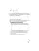
Opening and Closing the Front Rack Door To open the front rack door: 1 Press in on the handle lock cylinder where the key is inserted. See Figure 1. 2 After the handle is released, pull it upwards to release the door from the catches. See Figure 1. 3 Open the front door all the way. See Figure 1. To close the door: 1 Push the door frame evenly against the extension frame and ensure that the door is in contact with the extension frame. 2 Push the handle down to latch the door.
Figure 1. Removing the Front Door 2 1 3 4 5 1 handle 2 hinge pins (4) 3 hinge body 4 hinge-pin housings (4) 5 lock cylinder Replacing the Front Door To replace the front door, follow the steps for removing the front door in the reverse order.
Removing the Back Doors WARNING: Never attempt to remove or install the rack cabinet doors by yourself. Due to the size and weight of the rack cabinet doors, this procedure requires two people. 1 Rotate the door handle one-quarter turn clockwise to open the back doors. See Figure 2. Figure 2.
2 Remove the right back door. a While supporting the door, pull the pin for the top hinge out of the door’s hinge-pin housing. See Figure 3. You hear a click sound as you pull the pin out of the door’s hinge-pin housing. The hinge pins are designed to prevent them from being pulled out of the hinge body. b Repeat step a for the bottom hinge. c Pull the door away from the rack. Figure 3.
d Lay the door in a safe location with the door’s outer surface facing upward. NOTE: Lay the door flat with the outer surface facing upward to prevent damage to its cosmetic coating. 3 Repeat step a through step d for the left back door. Replacing the Back Doors To replace the back doors, follow the steps for removing the back doors in the reverse order. Removing and Replacing the Side Panels NOTE: Remove the lower side panels in order to install the side brushes and the side stabilizer feet.
Figure 4. Replacing the Upper Side Panels 1 2 3 1 panel lip 3 latches (2) 2 upper side panel Removing the Lower Side Panels 1 Pull both latches down and allow the side panel to swing outward slightly at the top. 2 Firmly grasp both sides of the panel. 3 Lift the panel upward until the panel hooks clear the holes in the bottom of the rack frame. 4 Place the panel in a safe location with the panel’s outer surface facing upward to prevent damage to its cosmetic coating.
Replacing the Lower Side Panels 1 Lower the panel into the rack, inserting the panel hook into the back hole in the bottom of the rack frame and the front hook into the corresponding hole in the front of the rack frame. See Figure 5. 2 Swing the top end of the panel toward the rack. 3 Press the panel into the rack until both latches lock into place. Figure 5.
Installing the Brushes WARNING: All brushes supplied must be installed and the brush bristles must be in contact with the floor to form a seal around the bottom perimeter of the rack enclosure. Removing the brushes may reduce the cooling efficiency within the enclosure. To install the brushes on the side of the rack: 1 Remove the lower side panel. See "Removing the Lower Side Panels" on page 14. 2 Align the brush bracket with the rack frame and insert the brush bracket into the rack frame. See Figure 6.
Figure 6.
Removing and Replacing the Extension Service Cover WARNING: The extension service cover must only be removed when installing or removing components from the upper rack unit spaces and must be reinstalled immediately. Components in the rack may overheat if the extension service cover is not installed in the rack enclosure. NOTE: Do not use the extension service cover as an outlet to route cables out of the rack.
Figure 7. Removing and Replacing the Extension Service Cover 1 2 4 3 1 studs (4) 2 extension service cover 3 wing nuts (4) 4 extension Replacing the Extension Service Cover 1 Align the studs with the holes in the extension and lower the extension service cover on to the top of the rack. See Figure 7. 2 Install the four wing nuts.
Removing and Replacing the Extension WARNING: Never attempt to remove or install the extension by yourself. Due to the size and weight of the extension, this procedure requires at least two people. Removing the Extension 1 Remove the front door. See "Removing the Front Door" on page 9. 2 Ensure that the extension service cover is installed. See Figure 8. 3 Remove the four thumb screws that secure the extension to the rack. 4 Lift the extension and slide it away from the rack. See Figure 8. Figure 8.
Replacing the Extension To replace the extension, perform the steps for removing the extension in the reverse order. Reversing the Front Door (Optional) To reverse the direction that the front door opens, complete the following steps: 1 Remove the front door. See "Removing the Front Door" on page 9. 2 Using a T30 Torx screwdriver and a 10 mm wrench, remove the screws that secure the hinges to the extension. See Figure 9.
Figure 9.
3 Using a T30 Torx screwdriver and a 10 mm wrench, remove the screws that secure the catches to the extension. See Figure 10. NOTE: While removing the screws, collect the loose nuts from the inside of the extension. NOTE: Each catch has an L character on one end and an R character at the other end. The catches are oriented such that the screw is installed in the top most hole for all the catches. The screws for the catches are installed in the hole that is closest to the L character. Figure 10.
4 Flip the catches and secure them on the opposite side of the extension using screws and nuts. See Figure 11. NOTE: You must orient the catches such that the screw is installed at the bottom most hole for all catches. The screw for each catch is installed in the hole that is closest to the L character. Figure 11.
5 Flip the hinges and secure them on the opposite side of the extension using screws and nuts. See Figure 12. The two hinges at the top have the number 1 marked on them and the bottom two hinges have the number 2 marked on them. NOTE: The orientation of the number 1 is right-side up and the orientation of the number 2 is upside down. NOTE: Each hinge is secured to the extension using only one screw and all the screws are installed in the top hinge hole. Figure 12.
6 Rotate the window. a Place the door down on the floor. b Using a 10 mm wrench, remove all the nuts that secure the window to the front door. See Figure 13. NOTE: It is recommended that you place the door on a smooth and clean surface in order to minimize risk of scratching the window and the Dell badge. c Remove the top and bottom end caps and slide the window out through the top or bottom end of the door. See Figure 13.
7 Replace the front door with the hinge pin housings located on the right and the latch located on the left side of the door. See Figure 14. Figure 14.
8 Rotate the handle. a Open the handle and ensure that the two screws are accessible. b Mark the linkage position relative to the inside door trim using a piece of tape or a marking device. See Figure 15. c Using a T20 Torx screwdriver, remove the two screws that secure the handle. See Figure 15. d Rotate the handle. See Figure 15. Figure 15.
Securing the Rack Leveling Feet WARNING: Read all statements below before you adjust the leveling feet. • The Energy Smart rack must be positioned above the perforated tiles. • Your rack includes four leveling feet, which are mounted near the corners of the rack frame. • The leveling feet are designed to align the rack in an upright, level position when the rack is placed on a slightly uneven floor surface. • Before you install your systems in the rack, adjust the leveling feet.
Figure 16.
Installing the Rack Stabilizer Feet WARNING: Installing systems in a rack without the front and side stabilizer feet installed could cause the rack to tip over, potentially resulting in bodily injury under certain circumstances. Therefore, always install the stabilizer feet before installing components in the rack. Install the stabilizer feet on the rack as follows: 1 Install the front and side stabilizer feet on a standalone rack.
Figure 17. Installing the Front Stabilizer Feet 1 1 front stabilizer feet (2) Installing the Side Stabilizer Feet NOTE: Ensure that all brushes are installed to maintain cooling efficiency. 1 Remove the lower side panels. See "Removing the Lower Side Panels" on page 14. 2 On the side of the rack frame’s bottom rail, locate the four bolts that attach the side brushes to the rack. See Figure 18. 3 Using a 6 mm Allen wrench, remove the washers and bolts for only one stabilizer.
6 Repeat the entire process to install stabilizer feet on the opposite side of the rack enclosure. See Figure 18. 7 Replace the lower side panels. See "Replacing the Lower Side Panels" on page 15. Figure 18.
Adjusting the Rear Rack Posts (Optional) NOTE: Do not move the front rack posts located on the rack enclosure. The position of the rack posts can be adjusted to accommodate systems of various depths. 1 Open the rack doors. 2 To remove the air channel from the rack, remove the two screws from the front flange (one per side) and two screws from the back of the rack using a #2 Phillips cross-tip screwdriver. See Figure 19.
4 Remove the screws from the bottom, middle, and top of the post. See Figure 20. 5 Move the post to the desired location inside the side of the rack and install the screws in the corresponding holes. Figure 20.
6 Reinstall the air channel by reversing the process used to remove the air channel. NOTE: The air channel must always remain at the bottom of the rack (in 1U and 2U) and must not be moved to a different location in the rack. NOTE: Unless you need to couple two or more racks, you may now install systems into the rack. For information on installing components in the rack, see the white numbered labels on the front and back of the rack mounting rails.
Figure 21.
Opening and Closing the Top Cable Slot The top cable slot in the rack can be used to route cables up to a cable raceway. 1 Open the back doors. 2 Loosen the wing nuts underneath the cable slot cover. See Figure 22. 3 Slide the cable slot cover toward the front of the rack. 4 Route the cables through the top of the rack. 5 Close any air gap in the cable slot by pulling the slot cover toward the back of the rack. 6 Secure the cover using the wing nuts.
Figure 22.
Removing and Installing the Back Door Stabilizer Bars The top and bottom bars used to stabilize the back doors can be removed, making it easier to route cables through the top and bottom of the rack. 1 Open the back doors. 2 Pull and hold the plungers on each side of the bar, and move the bar up and away from the rack. See Figure 23. 3 Route the cables and replace the bars by aligning the tabs on the bars with the corresponding holes in the rack. 4 Push the plungers until they lock into place. Figure 23.
Coupling Two Racks WARNING: Never attempt to remove or install the rack doors by yourself. Due to the size and weight of the rack cabinet doors, this procedure requires at least two people. WARNING: You must install the front stabilizer feet on the front of the racks and the outer sides, after the interconnect kit is in place. 1 Unpack and set up both racks. 2 Unpack the coupling kit. See Figure 24. The contents of the rack coupling kit include: • One gasket strip • Four coupling brackets Figure 24.
Figure 25.
5 Install the coupling brackets. a Position the two racks side by side. b Adjust the leveling feet on both racks so that the racks are parallel and in the same horizontal plane. For more information, see "Adjusting the Leveling Feet" on page 30. c Hook the brackets into the square holes inside and adjacent to the rack posts and tighten the brackets using the wing nuts. See Figure 26. 6 Install the front stabilizer feet. See "Installing the Front Stabilizer Feet" on page 31.
44 Installation Guide
Châssis du rack Dell Energy Smart Guide d'installation
Remarques, précautions et avertissements REMARQUE : Une REMARQUE indique des informations importantes qui peuvent vous aider à mieux utiliser votre ordinateur. PRÉCAUTION : Une PRÉCAUTION indique un risque de dommage matériel ou de perte de données en cas de non-respect des instructions données. AVERTISSEMENT : Un AVERTISSEMENT indique un risque potentiel d'endommagement du matériel, de blessure corporelle ou de mort.
Table des matières Consignes de sécurité . . . . . . . . . . . . . . . . . . SÉCURITÉ : Montage en rack des systèmes 49 . . . . 49 . . . . . . . . . . . 50 Spécifications du rack . . . . . . . . . . . . . . . 50 Avant de commencer . . . . . . . . . . . . . . . . 51 Instructions d'installation en rack . . . . . . . . 52 . . . . . . . . . . . 52 Outils et fournitures recommandés Installation des armoires rack Ouverture et fermeture de la porte avant du rack . . . . . . . . . . . . . . .
48 Table des matières
Consignes de sécurité Appliquez les consignes de sécurité fournies dans ce guide pour préserver votre sécurité personnelle et protéger votre équipement et votre environnement de travail de tout dommage. Pour plus d'informations sur la sécurité et les réglementations, reportez-vous aux consignes de sécurité fournies avec l'équipement. Les informations sur la garantie se trouvent dans ce document ou dans un document distinct.
• La conduite d'air située en bas du rack est utilisée pour diriger l'air froid du sol vers l'avant du châssis du rack. La conduite d'air doit toujours rester en bas du rack (pour les façades 1U et 2U) et ne doit pas être déplacée à un autre endroit du rack. • N'utilisez pas la conduite d'air comme une marche ou une étagère pour supporter des composants.
Avant de commencer AVERTISSEMENT : Avant de procéder à l'installation du rack, lisez attentivement la section «Consignes de sécurité importantes», à la page 51 ainsi que les consignes de sécurité fournies avec le rack. AVERTISSEMENT : Si vous installez plusieurs systèmes dans un même rack, effectuez toutes les opérations requises pour le système en cours d'installation avant de commencer l'installation du système suivant.
Outils et fournitures recommandés Pour installer le rack, vous pouvez avoir besoin des outils et fournitures suivants : • Tournevis cruciforme n°2 • Tournevis à tête plate • Clé de 12 mm • Clé de 10 mm (pour inverser le sens d'ouverture de la porte avant) • Tournevis Torx T20 (pour inverser le sens d'ouverture de la porte avant) • Tournevis Torx T30 (pour inverser le sens d'ouverture de la porte avant) • Clés des portes et des panneaux latéraux du rack • Clé Allen de 6 mm • Clé à molette (p
Ouverture et fermeture de la porte avant du rack Pour ouvrir la porte avant du rack : 1 Appuyez sur le barillet de la poignée où la clé est insérée. Voir figure 1. 2 Une fois la poignée libérée, poussez-le vers le haut pour dégager la porte des loquets. Voir figure 1. 3 Ouvrez entièrement la porte. Voir figure 1. Pour fermer la porte : 1 Poussez le châssis de la porte contre le châssis de l'extension et assurezvous que la porte est en contact avec ce dernier. 2 Abaissez la poignée pour verrouiller la porte.
Retrait et réinstallation des portes du rack AVERTISSEMENT : N'essayez pas de retirer ou de réinstaller les portes de l'armoire rack seul. En raison de la taille et du poids des portes de l'armoire rack, cette procédure nécessite au moins deux personnes. Retrait de la porte avant 1 Ouvrez la porte du rack. Voir «Ouverture et fermeture de la porte avant du rack», à la page 53. 2 Tout en maintenant la porte, retirez les axes de charnière en commençant par la partie inférieure du rack.
Figure 1. Retrait de la porte avant 2 1 3 4 5 1 poignée 2 axes de la charnière (4) 3 corps de la charnière 4 logements des axes de la charnière (4) 5 barillet Remise en place de la porte avant Pour réinstaller la porte avant, suivez les étapes de la procédure de retrait dans l'ordre inverse.
Retrait des portes arrière AVERTISSEMENT : N'essayez pas de retirer ou de réinstaller les portes de l'armoire rack seul. En raison de la taille et du poids des portes de l'armoire rack, cette procédure nécessite deux personnes. 1 Tournez la poignée d'un quart de tour dans le sens des aiguilles d'une montre pour ouvrir les portes arrière. Voir figure 2. Figure 2. Ouverture des portes arrière 1 2 1 poignée 2 portes arrière (2) 2 Retirez la porte arrière droite.
b Répétez l'étape a pour la charnière du bas. c Tirez sur la porte pour l'extraire. Figure 3. Retrait des portes arrière 1 2 3 1 axe de charnière 3 logement de l'axe de charnière 2 corps de la charnière AVERTISSEMENT : Compte tenu de la taille et du poids de la porte, il est recommandé de la poser à plat sur le sol, face externe vers le haut. d Déposez la porte en lieu sûr, face externe vers le haut. REMARQUE : En procédant ainsi, vous éviterez d'endommager le revêtement de la porte.
Réinstallation des portes arrière Pour réinstaller les portes arrière, suivez les étapes de la procédure de retrait dans l'ordre inverse. Retrait et réinstallation des panneaux latéraux REMARQUE : Retirez les panneaux latéraux pour installer les brosses latérales et les pieds stabilisateurs latéraux.
Figure 4. Réinstallation des panneaux latéraux supérieurs 1 2 3 1 lèvre 3 loquets (2) 2 panneau latéral supérieur Retrait des panneaux latéraux inférieurs 1 Abaissez les deux loquets et faites glisser le panneau vers le haut pour dégager légèrement sa partie supérieure. 2 Tenez fermement le panneau par ses côtés. 3 Relevez le panneau de façon à dégager les crochets des orifices situés en bas du châssis du rack.
Réinstallation des panneaux latéraux inférieurs 1 Introduisez le panneau dans le rack, en enclenchant le crochet dans l'orifice arrière situé en bas du châssis du rack et le crochet avant dans l'orifice correspondant à l'avant du châssis du rack. Voir figure 5. 2 Faites basculer la partie supérieure du panneau vers le rack. 3 Enfoncez le panneau dans le rack jusqu'à ce que les deux loquets s'enclenchent. Figure 5.
Installation des brosses AVERTISSEMENT : Toutes les brosses fournies doivent être installées et les poils des brosses doivent être en contact avec le sol pour former un joint autour du périmètre inférieur du châssis du rack. Le retrait des brosses peut réduire le refroidissement dans le châssis. Pour installer les brosses sur le côté du rack : 1 Retirez le panneau latéral inférieur. Voir «Retrait des panneaux latéraux inférieurs», à la page 59.
Figure 6.
Retrait et remplacement de l'extension du capot de service AVERTISSEMENT : L'extension du capot de service doit uniquement être retirée lors de l'installation ou du retrait des composants des espaces supérieurs de l'unité de rack et doit être réinstallée immédiatement. Les composants peuvent surchauffer si l'extension du capot de service n'est pas installée dans l'armoire rack. REMARQUE : N'utilisez pas l'extension du capot de service en tant que prise pour acheminer les câbles hors du rack.
Figure 7. Retrait et remplacement de l'extension du capot de service 1 2 4 3 1 goujons (4) 2 extension du capot de service 3 écrous à oreille (4) 4 extension Replacement de l'extension du capot de service 1 Alignez les goujons avec les trous de l'extension et abaissez l'extension du capot de service sur la partie supérieure du rack. Voir figure 7. 2 Placez les quatre écrous à oreilles.
Retrait et remplacement de l'extension AVERTISSEMENT : N'essayez jamais de retirer ou d'installer l'extension seul. En raison de la taille et du poids de l'extension, cette procédure nécessite au moins deux personnes. Retrait de l'extension 1 Retirez la porte avant. Voir «Retrait de la porte avant», à la page 54. 2 Assurez-vous que l'extension du capot de service est installée. Voir figure 8. 3 Retirez les quatre vis à oreilles qui fixent l'extension au rack. 4 Soulevez l'extension et retirez-la du rack.
Replacement de l'extension Pour replacer l'extension, répétez les étapes de la procédure de retrait dans l'ordre inverse. Inversion du sens d'ouverture de la porte avant (facultatif) Pour inverser le sens d'ouverture de la porte avant, procédez comme suit : 1 Retirez la porte avant. Voir «Retrait de la porte avant», à la page 54. 2 À l'aide d'un tournevis Torx T30 et d'une clé de 10 mm, retirez les vis qui fixent les charnières à l'extension. Voir figure 9.
Figure 9.
3 À l'aide d'un tournevis Torx T30 et d'une clé de 10 mm, retirez les vis qui fixent les loquets à l'extension. Voir figure 10. REMARQUE : Lors du retrait des vis, récupérez les écrous desserrés provenant de l'intérieur de l'extension. REMARQUE : Sur chaque loquet, le caractère «L» est indiqué d'un côté et «R» de l'autre. Les loquets sont orientés afin que la vis soit installée dans l'orifice le plus haut de chacun. Les vis des loquets sont placées dans l'orifice le plus proche du caractère «L». Figure 10.
4 Retournez les loquets et fixez-les sur le côté opposé de l'extension à l'aide des vis et des boulons. Voir figure 11. REMARQUE : Vous devez orienter les loquets afin que la vis soit installée dans l'orifice le plus bas de chacun. La vis de chaque loquet est placée dans l'orifice le plus proche du caractère «L». Figure 11.
5 Retournez les charnières et fixez-les sur le côté opposé de l'extension à l'aide des vis et des boulons. Voir figure 12. Les deux charnières supérieures sont marquées du numéro 1 et les deux charnières inférieures du numéro 2. REMARQUE : La position du numéro 1 est à l'envers et celle du numéro 2 à l'endroit. REMARQUE : Chaque charnière est fixée à l'extension à l'aide d'une seule vis et toutes les vis sont placées dans l'orifice de la charnière supérieure. Figure 12.
6 Faites pivoter la fenêtre. a Placez la porte sur le sol. b À l'aide d'une clé de 10 mm, retirez tous les écrous qui maintiennent la fenêtre à la porte avant. Voir figure 13. REMARQUE : Il est recommandé de placer la porte sur une surface lisse et propre afin de minimiser le risque de rayures sur la fenêtre et le macaron Dell. c Retirez les embouts supérieurs et inférieurs et faites glisser la fenêtre par le haut ou le bas de la porte. Voir figure 13.
Figure 14. Installation de la porte avant 1 1 porte avant 8 Tournez la poignée. 72 a Ouvrez la poignée et assurez-vous que les deux vis sont accessibles. b Marquez d'un repère la position relative à la garniture intérieure de la porte à l'aide d'un morceau de bande adhésive ou d'un marqueur. Voir figure 15. c À l'aide d'un tournevis Torx T20, retirez les deux vis qui fixent la poignée. Voir figure 15. d Tournez la poignée. Voir figure 15.
Figure 15. Rotation de la poignée de la porte avant 2 1 1 poignée e 2 vis (2) Alignez les orifices de la poignée et placez les vis, tout en plaçant la poignée en position d'ouverture et en alignant les repères. Voir figure 15. REMARQUE : Si un morceau de bande adhésive a été utilisé pour faires les repères, retirez-le.
Fixation des pieds réglables de l'armoire AVERTISSEMENT : Lisez toutes les instructions ci-après avant de régler les pieds de l'armoire. • Le rack à consommation d'énergie intelligente doit être positionné sur les panneaux perforés. • Votre rack est équipé de quatre pieds réglables, un près de chaque coin du châssis de l'armoire. • Ils permettent de maintenir le rack parfaitement droit, même sur une surface légèrement inégale.
2 Pour abaisser davantage le pied, resserrez l'écrou 6 pans à l'aide d'une clé de 12 mm. Voir figure 16. 3 Répétez la procédure de l'étape 1 et l'étape 2 pour les autres pieds réglables. 4 Vérifiez que le rack est bien de niveau. Figure 16.
Installation des pieds stabilisateurs AVERTISSEMENT : Si vous installez des composants dans un rack sans avoir installé les pieds stabilisateurs avant et latéraux, vous risquez de voir tout l'édifice basculer, causant éventuellement des dommages corporels. C'est pourquoi, il faut toujours monter les pieds stabilisateurs avant d'installer les composants du rack.
Figure 17. Installation des pieds stabilisateurs avant 1 1 pieds stabilisateurs avant (2) Installation des pieds stabilisateurs latéraux REMARQUE : Assurez-vous que toutes les brosses sont installées pour un refroidissement efficace. 1 Retirez les panneaux latéraux inférieurs. Voir «Retrait des panneaux latéraux inférieurs», à la page 59. 2 Sur le côté du rail inférieur du cadre du rack, repérez les quatre boulons qui maintiennent les brosses latérales au rack. Voir figure 18.
5 Répétez la procédure de l' étape 3 et l' étape 4 pour installer le second pied stabilisateur sur le même côté. 6 Recommencez l'ensemble de la procédure pour installer les pieds stabilisateurs de l'autre côté du châssis du rack. Voir figure 18. 7 Replacez les panneaux latéraux inférieurs. Voir «Réinstallation des panneaux latéraux inférieurs», à la page 60. Figure 18.
Réglage des montants arrière du rack (facultatif) REMARQUE : Ne déplacez jamais les montants avant du rack situés sur le châssis. Vous pouvez régler la position des montants pour accueillir des systèmes de profondeurs diverses. 1 Ouvrez les portes du rack. 2 Pour retirer la conduite d'air du rack, retirez les deux vis de la collerette avant (une par côté) et les deux vis de l'arrière du rack en utilisant un tournevis cruciforme n°2. Voir figure 19.
4 Retirez les vis des parties supérieure, centrale et inférieure du montant. Voir figure 20. 5 Positionnez le montant à l'emplacement souhaité à l'intérieur du rack et placez les vis dans les trous correspondants. Figure 20.
6 Réinstallez la conduite d'air en inversant la procédure utilisée pour retirer la conduite d'air. REMARQUE : La conduite d'air doit toujours rester en bas du rack (pour les façades 1U et 2U) et ne doit pas être déplacée à un autre endroit du rack. REMARQUE : Si vous n'envisagez pas de joindre plusieurs racks, vous pouvez dès à présent commencer à installer vos systèmes.
Figure 21.
Ouverture et fermeture de la sortie câbles supérieure Vous pouvez utiliser la sortie câbles supérieure pour acheminer les câbles vers un chemin de câbles. 1 Ouvrez les portes arrière. 2 Dévissez les écrous à oreilles situés sous le couvercle de la sortie câbles. Voir figure 22. 3 Faites glisser le couvercle de la sortie de câbles vers l'avant du rack. 4 Acheminez les câbles vers le haut du rack 5 Refermez le couvercle en le faisant glisser vers l'arrière du rack.
Figure 22.
Retrait et installation des barres de stabilisation des portes arrière Vous pouvez retirer les barres de stabilisation inférieure et supérieure des portes arrière pour faciliter le passage des câbles. 1 Ouvrez les portes arrière. 2 Contractez et maintenez les pistons plongeurs de chaque côté de la barre, puis soulevez celle-ci pour la dégager du rack. Voir figure 23. 3 Acheminez les câbles et remettez les barres en place en alignant leurs languettes avec les trous correspondant du rack.
Couplage de deux armoires AVERTISSEMENT : N'essayez pas de retirer ou de réinstaller les portes du rack seul. En raison de la taille et du poids des portes de l'armoire rack, cette procédure nécessite au moins deux personnes. AVERTISSEMENT : Après avoir installé le kit interconnexion, vous devez installer les pieds stabilisateurs avant sur la partie avant des racks et les parties externes. 1 Retirez les deux armoires de leur emballage et installez-les. 2 Retirez le kit de couplage de son emballage.
Figure 25.
5 Fixez les supports de couplage. a Positionnez les deux racks côte à côte. b Ajustez les pieds réglables pour que les racks soient parallèles et sur le même plan horizontal. Pour plus d'informations, voir «Ajustement des pieds réglables», à la page 75. c Accrochez les supports dans les trous carrés situés dans et à côté des montants du rack, puis fixez les supports au moyen des écrous à oreilles. Voir figure 26. 6 Installez les pieds stabilisateurs avant.
Dell Energy SmartRackgehäuse Installationsanleitung
Anmerkungen, Vorsichtshinweise und Warnungen ANMERKUNG: Eine ANMERKUNG macht auf wichtige Informationen aufmerksam, mit denen Sie den Computer besser einsetzen können. VORSICHTSHINWEIS: Ein VORSICHTSHINWEIS weist auf mögliche Gefahrenquellen hin, die Hardwareschäden oder Datenverlust zur Folge haben können, wenn die Anweisungen nicht befolgt werden.
Inhalt Sicherheitshinweise. . . . . . . . . . . . . . . . . . . SICHERHEIT: Einbauen von Systemen im Rack . . . 93 . . . . . . . . . . . . . 94 . . . . . . . . . . . . . . . 94 . . . . . . . . . . . . . . . . 95 Anleitung für die Rackmontage Rack-Spezifikationen . Bevor Sie beginnen . . . . . . . . 96 . . . . . . . . . . 97 Empfohlene Werkzeuge und Zubehör Installation von Rackschränken . . . 97 . . . . . 98 . . . . . . . . . 102 . . . . . . . . . . . . . .
92 Inhalt
Sicherheitshinweise Beachten Sie die nachfolgenden Sicherheitshinweise, um Ihre eigene Sicherheit zu gewährleisten und eine mögliche Beschädigung des Systems und der Arbeitsumgebung zu vermeiden. Die vollständigen Informationen zu Sicherheitsanforderungen und Betriebsvorschriften finden Sie in den Sicherheitshinweisen, die Sie mit dem System erhalten haben. Garantieinformationen können in diesem Dokument enthalten oder als separates Dokument beigelegt sein.
• Der Luftkanal an der Unterseite des Racks dient dazu, kühle Luft vom Boden zur Vorderseite des Rackgehäuses zu leiten. Der Luftkanal muss immer an dere Unterseite des Racks bleiben (in 1U und 2U) und darf nicht an eine andere Stelle im Rack versetzt werden. • Verwenden Sie den Luftkanal nicht als Trittstufe oder zum Abstützen von Komponenten.
Bevor Sie beginnen WARNUNG: Lesen Sie aufmerksam den Abschnitt „Wichtige Sicherheitshinweise“ auf Seite 96 sowie die Sicherheitsanweisungen, die Sie mit dem Rack erhalten haben. WARNUNG: Wenn Sie mehrere Systeme in einem Rack installieren, schließen Sie alle Maßnahmen für ein System ab, bevor Sie das nächste System installieren. WARNUNG: Rackschränke können sehr schwer sein und leicht wegrollen. Die Schränke haben keine Bremsen. Bewegen Sie den Rackschrank nur mit größter Vorsicht.
Wichtige Sicherheitshinweise Beachten Sie beim Einbau des Systems im Rack die Sicherheitsmaßnahmen in den folgenden Unterabschnitten. WARNUNG: Befolgen Sie die in diesem Dokument angegebenen Vorgehensweisen genau, um sich selbst und andere Personen nicht zu gefährden. Das System ist möglicherweise sehr groß und schwer. Sie sollten die Installation sorgfältig vorbereiten und planen, um Verletzungen vorzubeugen. Dies gilt besonders, wenn Systeme weiter oben im Rack installiert werden.
Installation von Rackschränken Die Installation eines Rackschranks kann folgende Schritte umfassen: 1 Öffnen und Schließen der vorderen Racktür 2 Entfernen und Wiederanbringen der Racktüren 3 Entfernen und Wiederanbringen der Seitenteile 4 Installieren der Bürsten 5 Entfernen und Wiederanbringen der Wartungsabdeckung für die Erweiterung 6 Entfernen und Wiederanbringen der Erweiterung 7 Umgekehrtes Einbauen der vorderen Tür 8 Einstellen der höhenverstellbaren Rackfüße 9 Anbringen der Stabilisatoren 10 Anpass
Entfernen und Installieren der Racktüren WARNUNG: Versuchen Sie niemals, die Türen des Rackschranks alleine zu entfernen oder zu installieren. Aufgrund der Größe und des Gewichts der Türen sind für diesen Arbeitsschritt mindestens zwei Personen erforderlich. Abnehmen der vorderen Tür 1 Öffnen Sie die Racktür. Siehe „Öffnen und Schließen der vorderen Racktür“ auf Seite 97. 2 Halten Sie die Tür fest und entfernen Sie die Scharnierstifte, indem Sie unten am Rack beginnen.
Abbildung 1. Vordere Tür abnehmen 2 1 3 4 5 1 Griff 2 Scharnierstifte (4) 3 Scharniergehäuse 4 Scharnierstiftgehäuse (4) 5 Schließzylinder Wiederanbringen der vorderen Tür Um die vordere Tür wieder anzubringen, befolgen Sie die Anweisungen zum Abnehmen der vorderen Tür in umgekehrter Reihenfolge.
Abnehmen der hinteren Türen WARNUNG: Versuchen Sie niemals, die Türen des Rackschranks alleine zu entfernen oder zu installieren. Aufgrund der Größe und des Gewichts der Türen sind für diesen Arbeitsschritt mindestens zwei Personen erforderlich. 1 Drehen Sie den Türgriff um eine Vierteldrehung im Uhrzeigersinn, um die hinteren Türen zu öffnen. Siehe Abbildung 2. Abbildung 2. Hintere Türen öffnen 1 2 1 Türgriff 2 Hintere Türen (2) 2 Nehmen Sie die rechte hintere Tür ab.
b Wiederholen Sie Schritt a für das untere Scharnier. c Ziehen Sie die Tür von dem Rack weg. Abbildung 3. Hintere Türen abnehmen 1 2 3 1 Scharnierstift 3 Scharnierstiftgehäuse 2 Scharniergehäuse WARNUNG: Wegen der Größe und des Gewichts der Tür wird empfohlen, diese nach dem Abnehmen mit der Außenfläche nach oben flach hinzulegen. d Bewahren Sie die Tür mit der Außenfläche nach oben an einem sicheren Platz auf.
Wiederanbringen der hinteren Türen Um die hinteren Türen wieder anzubringen, befolgen Sie die Anweisungen zum Abnehmen der hinteren Türen in umgekehrter Reihenfolge. Abnehmen und Wiederanbringen der Seitenteile ANMERKUNG: Nehmen Sie die unteren Seitenteile ab, um die seitlichen Bürsten und die seitlichen Stabilisatoren installieren zu können. ANMERKUNG: Für die Installation von Systemen in einem Rack ist es nicht absolut erforderlich, die Seitenteile abzunehmen.
Abbildung 4. Obere Seitenteile wiederanbringen 1 2 3 1 Seitenteillasche 3 Sperrklinken (2) 2 Oberes Seitenteil Abnehmen der unteren Seitenteile 1 Ziehen Sie beide Sperrklinken nach unten und lassen Sie das Seitenteil oben etwas nach außen klappen. 2 Fassen Sie beide Kanten des Seitenteils fest an. 3 Heben Sie das Seitenteil nach oben, bis die Haken des Seitenteils nicht mehr in den Öffnungen unten am Rackrahmen sitzen.
Wiederanbringen der unteren Seitenteile 1 Setzen Sie das Seitenteil in das Rack. Achten Sie darauf, dass der hintere Haken am Seitenteil in die hintere Öffnung unten am Rackrahmen und der vordere Haken am Seitenteil in die entsprechende Öffnung auf der Vorderseite des Rackrahmens eingesetzt wird. Siehe Abbildung 5. 2 Klappen Sie das obere Ende des Seitenteils zum Rack hin. 3 Drücken Sie das Seitenteil in das Rack, bis beide Sperrklinken einrasten. Abbildung 5.
Installation der Bürsten WARNUNG: Alle Bürsten müssen installiert werden und ihre Borsten müssen dabei den Boden berühren, damit entlang des unteren Randes des Rackgehäuses eine Abdichtung geschaffen wird. Das Entfernen der Bürsten kann zu einer reduzierten Kühlleistung innerhalb des Gehäuses führen. So installieren Sie die Bürsten an der Seite des Racks: 1 Nehmen Sie das untere Seitenteil ab. Siehe „Abnehmen der unteren Seitenteile“ auf Seite 103.
Abbildung 6.
Entfernen und Wiederanbringen der Wartungsabdeckung für die Erweiterung WARNUNG: Die Wartungsabdeckung für die Erweiterung darf nur entfernt werden, wenn Komponenten in den oberen Einschüben der Rackeinheit installiert oder daraus entfernt werden. Danach muss die Abdeckung umgehend wieder angebracht werden. Wenn die Wartungsabdeckung für die Erweiterung nicht im Rackgehäuse installiert ist, kann es zu einer Überhitzung von Komponenten im Rack kommen.
Abbildung 7. Wartungsabdeckung für die Erweiterung entfernen und wiederanbringen 1 2 4 3 1 Stiftschrauben (4) 2 Wartungsabdeckung für die Erweiterung 3 Flügelmuttern (4) 4 Erweiterung Wiederanbringen der Wartungsabdeckung für die Erweiterung 1 Richten Sie die Stiftschrauben an den Öffnungen in der Erweiterung aus und lassen Sie die Wartungsabdeckung für die Erweiterung auf die Oberseite des Racks herab. Siehe Abbildung 7. 2 Bringen Sie die vier Flügelmuttern an.
Entfernen und Wiederanbringen der Erweiterung WARNUNG: Versuchen Sie niemals, die Erweiterung alleine zu entfernen oder wiederanzubringen. Aufgrund der Größe und des Gewichts der Erweiterung sind für diesen Arbeitsschritt mindestens zwei Personen erforderlich. Entfernen der Erweiterung 1 Nehmen Sie die vordere Tür ab. Siehe „Abnehmen der vorderen Tür“ auf Seite 98. 2 Vergewissern Sie sich, dass die Wartungsabdeckung für die Erweiterung installiert ist. Siehe Abbildung 8.
Wiederanbringen der Erweiterung Um die Erweiterung wieder anzubringen, befolgen Sie die Anweisungen zum Entfernen der Erweiterung in umgekehrter Reihenfolge. Umgekehrtes Einbauen der vorderen Tür (optional) Führen Sie die folgenden Schritte durch, um den Anschlag der Tür so zu ändern, dass sie sich in entgegengesetzter Richtung öffnet: 1 Nehmen Sie die vordere Tür ab. Siehe „Abnehmen der vorderen Tür“ auf Seite 98.
Abbildung 9.
3 Entfernen Sie mit einem Torx-Schraubendreher T-30 und einem 10-mmSchraubenschlüssel die Schrauben, mit denen die Verriegelungen an der Erweiterung befestigt sind. Siehe Abbildung 10. ANMERKUNG: Sammeln Sie beim Entfernen der Schrauben die losen Muttern aus dem Inneren der Erweiterung auf. ANMERKUNG: Jede Verriegelung zeigt an einem Ende den Buchstaben L und an dem anderen Ende den Buchstaben R.
4 Drehen Sie die Verriegelungen um 180 Grad und befestigen Sie sie mit Schrauben und Muttern an der entgegengesetzten Seite der Erweiterung. Siehe Abbildung 11. ANMERKUNG: Sie müssen die Verriegelungen so ausrichten, dass die Schraube bei allen Verriegelungen im untersten Loch installiert wird. Die Schrauben für die Verriegelungen werden in dem Loch installiert, das dem Buchstaben L am nächsten liegt. Abbildung 11.
5 Drehen Sie die Scharniere um 180 Grad und befestigen Sie sie mit Schrauben und Muttern an der entgegengesetzten Seite der Erweiterung. Siehe Abbildung 12. Die zwei oberen Scharniere sind mit der Zahl 1 gekennzeichnet, während die zwei unteren Scharniere die Zahl 2 aufweisen. ANMERKUNG: Die Zahl 1 ist richtig ausgerichtet, während die Zahl 2 auf dem Kopf steht. ANMERKUNG: Jedes Scharnier ist nur mit einer einzigen Schraube an der Erweiterung befestigt.
6 Drehen Sie die Sichtscheibe. a Legen Sie die Tür auf dem Boden ab. b Entfernen Sie mit einem 10-mm-Schraubenschlüssel sämtliche Muttern, mit denen die Sichtscheibe an der vorderen Tür befestigt ist. Siehe Abbildung 13. ANMERKUNG: Es wird empfohlen, die Tür auf eine glatte und saubere Oberfläche zu legen, um das Risiko von Kratzern auf der Sichtscheibe und dem Dell-Etikett zu minimieren.
Abbildung 13.
7 Bringen Sie die vordere Tür wieder an, mit den Scharnierstiftgehäusen auf der rechten Seite der Tür und der Sperrklinke auf der linken Seite. Siehe Abbildung 14. Abbildung 14.
8 Drehen Sie den Griff um 180 Grad. a Öffnen Sie den Griff und stellen Sie sicher, dass die beiden Schrauben zugänglich sind. b Markieren Sie mit einem Stück Klebeband oder einem Marker die Verbindungsstelle relativ zur Innenverkleidung der Tür. Siehe Abbildung 15. c Entfernen Sie mit einem Torx-Schraubendreher T-20 die beiden Schrauben, mit denen der Griff befestigt ist. Siehe Abbildung 15. d Drehen Sie den Griff um 180 Grad. Siehe Abbildung 15. Abbildung 15.
e Richten Sie die Grifflöcher bei geöffnetem Griff an den Verbindungsmarkierungen aus und installieren Sie die Schrauben. Siehe Abbildung 15. ANMERKUNG: Wenn zum Markieren der Verbindungsstellen ein Stück Klebeband verwendet wurde, entfernen Sie das Klebeband. Einstellen der höhenverstellbaren Rackfüße WARNUNG: Lesen Sie die folgenden Anweisungen komplett durch, bevor Sie mit dem Anpassen der höhenverstellbaren Füße beginnen. • Das Energy Smart-Rack muss über den Lochplatten platziert werden.
ANMERKUNG: Ist das Rack nicht korrekt ausgerichtet, können die Stabilisatoren eventuell nicht angebracht werden. Ohne Stabilisatoren kann das Rack jedoch umkippen. ANMERKUNG: Stellen Sie sicher, dass alle Bürsten installiert sind, um eine wirksame Kühlung zu gewährleisten. 1 Senken Sie mit einem Schraubendreher den Fuß, bis er auf dem Boden aufliegt. 2 Um den Fuß noch weiter zu senken, ziehen Sie die Sechskantmutter mit einem 12-mm-Schraubenschlüssel im Uhrzeigersinn fest. Siehe Abbildung 16.
Abbildung 16.
Anbringen der Stabilisatoren WARNUNG: Werden Systeme in einem Rack installiert, an dem die vorderen und seitlichen Stabilisatoren fehlen, kann das Rack umkippen, was unter Umständen schwere Verletzungen nach sich ziehen kann. Befestigen Sie daher immer zuerst die Stabilisatoren, bevor Sie Komponenten im Rack installieren. Befestigen Sie die Stabilisatoren in folgender Reihenfolge am Rack: 1 Bringen Sie bei einem freistehenden Rack auf der Vorderseite und an den Seiten Stabilisatoren an.
Abbildung 17. Vordere Stabilisatoren anbringen 1 1 Vordere Stabilisatoren (2) Anbringen der seitlichen Stabilisatoren ANMERKUNG: Stellen Sie sicher, dass alle Bürsten installiert sind, um eine wirksame Kühlung zu gewährleisten. 1 Nehmen Sie die unteren Seitenteile ab. Siehe „Abnehmen der unteren Seitenteile“ auf Seite 103. 2 Lokalisieren Sie an der Seite der unteren Schiene des Rackrahmens die vier Schrauben, mit denen die seitlichen Bürsten am Rack befestigt sind. Siehe Abbildung 18.
5 Wiederholen Sie Schritt 3 und Schritt 4, um den zweiten Stabilisator auf derselben Seite anzubringen. 6 Wiederholen Sie den ganzen Vorgang, um Stabilisatoren auf der anderen Seite des Rackgehäuses anzubringen. Siehe Abbildung 18. 7 Bringen Sie die unteren Seitenteile wieder an. Siehe „Wiederanbringen der unteren Seitenteile“ auf Seite 104. Abbildung 18.
Anpassen der hinteren Rackstützen (optional) ANMERKUNG: Verschieben Sie nicht die hinteren Rackstützen am Rackgehäuse. Die Stellungen der Rackstützen lassen sich an Systeme mit unterschiedlicher Tiefe anpassen. 1 Öffnen Sie die Türen des Racks. 2 Um den Luftkanal aus dem Rack zu entfernen, entfernen Sie mit einem Phillips Kreuzschlitzschraubenzieher PH 2 die beiden Schrauben vom vorderen Flansch (eine pro Seite) und zwei Schrauben von der Rückseite des Racks. Siehe Abbildung 19.
Abbildung 19.
4 Entfernen Sie die Schrauben von der Unterseite, der Mitte und der Oberseite der Stütze. Siehe Abbildung 20. 5 Verschieben Sie die Stütze zur gewünschten Position auf der Seitenfläche des Racks und installieren Sie die Schrauben in den entsprechenden Löchern. Abbildung 20.
6 Bringen Sie den Luftkanal wieder an, indem Sie den Vorgang umkehren, den Sie zum Entfernen des Luftkanals durchlaufen haben. ANMERKUNG: Der Luftkanal muss immer am Boden des Racks bleiben (in 1U und 2U) und darf nicht an eine andere Stelle im Rack versetzt werden. ANMERKUNG: Falls Sie nicht zwei oder mehrere Racks verbinden müssen, können Sie jetzt mit der Installation von Systemen im Rack beginnen.
Abbildung 21.
Öffnen und Schließen des oberen Kabelschlitzes Der obere Kabelschlitz im Rack kann benutzt werden, um Kabel bis zu einem Kabelkanal zu führen. 1 Öffnen Sie die hinteren Türen. 2 Lösen Sie die Flügelmuttern unter der Kabelschlitzabdeckung. Siehe Abbildung 22. 3 Schieben Sie die Kabelschlitzabdeckung in Richtung der Vorderseite des Racks. 4 Führen Sie die Kabel durch die Oberseite des Racks. 5 Schließen Sie jede Lücke im Kabelschlitz, indem Sie die Schlitzabdeckung zur Rückseite des Racks ziehen.
Abbildung 22.
Entfernen und Installieren der Stabilisierungsstege für die hintere Tür Die oberen und unteren Stege, die die hinteren Türen stabilisieren, lassen sich entfernen, um das Verlegen der Kabel durch die Oberseite und Unterseite des Racks zu erleichtern. 1 Öffnen Sie die hinteren Türen. 2 Ziehen und halten Sie die Stöpsel auf beiden Seiten des Stegs und ziehen Sie den Steg nach oben und weg vom Rack. Siehe Abbildung 23.
Verbinden von zwei Racks WARNUNG: Versuchen Sie niemals, die Türen des Racks alleine abzunehmen oder anzubringen. Aufgrund der Größe und des Gewichts der Türen sind für diesen Arbeitsschritt mindestens zwei Personen erforderlich. WARNUNG: Nachdem dem Einsatz des Verbindungskits müssen Sie die vorderen Stabilisatoren an der Vorderseite der Racks und an den Außenseiten anbringen. 1 Packen Sie beide Racks aus und stellen Sie sie auf. 2 Entpacken Sie das Verbindungskit. Siehe Abbildung 24.
ANMERKUNG: Stellen Sie sicher, dass der Dichtungsstreifen nicht auf der Erweiterung angebracht wird. ANMERKUNG: Sie können die Streifenabschnitte auf einem beliebigen Rack anbringen, solange durch die Streifen beide Racks vor Kratzern geschützt werden. Abbildung 25.
5 Installieren Sie die Kupplungsklammern. a Stellen Sie die beiden Racks nebeneinander. b Stellen Sie die höhenverstellbaren Füße beider Racks so ein, dass sich die Racks auf derselben Höhe befinden und parallel nebeneinander stehen. Weitere Informationen finden Sie unter „Höhenverstellbare Füße anpassen“ auf Seite 121. c Setzen Sie die Klammern in die viereckigen Öffnungen im Inneren der und neben den Rackstützen ein und ziehen Sie die Klammern mit den Flügelschrauben fest. Siehe Abbildung 26.
Abbildung 26.
Dell Energy Smart ラックエ ンクロージャ 設置ガイド
メモ、注意、警告 メモ:コンピュータを使いやすくするための重要な情報を説明してい ます。 注意:手順に従わないと、ハードウェアの損傷やデータの損失につながる 可能性があることを示しています。 警告: 物的損害、けが、または死亡の原因となる可能性があることを示 しています。 ____________________ 本書の内容は予告なく変更されることがあります。 © 2011 すべての著作権は Dell Inc. にあります。 Dell Inc. の書面による許可のない複製は、いかなる形態においても厳重に禁じられてい ます。 本書に使用されている商標:Dell™、DELL ロゴ、および PowerEdge™ は Dell Inc. の商標 です。 商標または製品の権利を主張する事業体を表すためにその他の商標および社名が使用され ていることがあります。それらの商標や会社名は、一切 Dell Inc. に帰属するものではあり ません。 2011 年 4 月 P/N GY60R Rev.
目次 安全にお使いいただくために . . . . . . . . . . . . 安全について:システムのラック への取り付け . . . . . . . . . . . . . . . . . . . 141 . . . . . . . . . . . . . . . . 142 . . . . . . . . . . . . . . . . . . . 142 ラックの取り付け手順 ラックの仕様 141 作業を開始する前に . . . . . . . . . . . . . . . 奨励するツールおよび備品 . . . . . . . . . . . 144 . . . . . . . . . . . . . . . 145 ラックの扉の取り外しと取り付け . . . . . . . 145 . . . . . 149 . . . . . . . . . . . . . . . . 152 サイドパネルの取り外しと取り付け ブラシの取り付け 144 . . . . . . . .
140 目次
安全にお使いいただくために ご自身の身体の安全を守り、装置および作業環境を保護するために、 以下の安全に関するガイドラインに従ってください。安全および認可機 関に関する詳細情報は、装置に付属しているマニュアルの安全にお使い いただくための注意事項を参照してください。保証情報は、このマニュ アルに含まれている場合と、別の文書として付属する場合があります。 安全について:システムのラックへの取り付け ラックの安定性や安全性に関して、以下の点にご注意ください。また、 特定の注意文および手順については、システムおよびラックに付属の ラック取り付けマニュアルを参照してください。 システムはラックの一部とみなします。「コンポーネント」には、 さまざまな周辺機器やサポートハードウェアと同様に、システムも含ま れます。 注意:ラックに取り付けるシステムの注意事項 • お使いのラックキットは、ご購入いただいたラックキャビネット専 用として承認されています。装置をその他のラックに取り付ける場 合は、ユーザーの責任において、適用されるすべての基準に適合す ることを確認してください。デルでは、本製品以外のラックとの組 み合わせは
• 床からラックエンクロージャの前面に冷風を流すために、ラック底 部のエアーチャネルが使われます。エアーチャネルは常にラックの 底部(1U および 2U)に取り付けておいてください。ラック内の別 の位置に移動しないでください。 • エアーチャネルをコンポーネント用の棚や踏み台として使用しない でください。 警告:付属のブラシはすべて取り付けます。ブラシの剛毛が床と接触し、 ラックエンクロージャの底部周囲を密閉している必要があります。ブラシ を取り外すと、エンクロージャ内の冷却効率が低下する可能性があり ます。 警告:エクステンションサービスカバーは、ラックユニットの上部ス ペースでコンポーネントの取り付けや取り外しを行う場合にのみ取り外 し、コンポーネントの取り付けや取り外しを終えたら、直ちに取り付けて ください。エクステンションサービスカバーがラックエンクロージャに取 り付けられていないと、ラック内のコンポーネントがオーバーヒートする おそれがあります。 ラックの取り付け手順 この設置ガイドは、ラックエンクロージャの設置作業を行う、トレーニ ングを受けたサービス技術者向けの手順書です。本書では、ラッ
作業を開始する前に 警告:ラックへの取り付け作業を開始する前に、143 ページの「安全に関 する重要な注意」、およびラックに付属しているガイドの安全にお使いい ただくための注意事項をよくお読みください。 警告:複数のシステムをラックに取り付ける場合は、1 台のシステムの取 り付け手順を完了してから、次のシステムの取り付けに進んでください。 警告:ラックキャビネットはサイズが非常に大きく重量もありますが、 キャスターで簡単に移動できるようになっています。このキャスターには ブレーキがありません。ラックキャビネットを移動するときは十分な注意 が必要です。ラックキャビネットを別の場所に移動するときは、水平調節 用の脚を収納してください。長い傾斜面、急勾配、または凹凸のある場 所、スロープなど、バランスが取りにくい場所にはキャビネットを設置し ないでください。水平調節用の脚を伸ばしてキャビネットを支え、キャビ ネットが動かないようにしてください。 警告:ラックキャビネットの移動を凹凸のある場所で行わないでくだ さい。キャスターが強い衝撃を受けて壊れ、ラックが不安定になって転倒 するおそれがあります。 警告:コンポーネ
奨励するツールおよび備品 ラックを取り付けるには、以下のツールと備品が必要です。 • #2 プラスドライバ • マイナスドライバ • 12 mm レンチ • 10 mm レンチ(前面扉を逆向きにする際に使用) • T20 トルクスドライバ(前面扉を逆向きにする際に使用) • T30 トルクスドライバ(前面扉を逆向きにする際に使用) • ラックの扉とサイドパネルのキー • 6 mm アレンレンチ • 可動レンチ(ラックをパレットから取り外す際に使用) ラックキャビネットの取り付け ラックキャビネットの取り付けでは、以下の作業を行います。 1 ラック前面扉の開閉 2 ラックの扉の取り外しと取り付け 3 サイドパネルの取り外しと取り付け 4 ブラシの取り付け 5 エクステンションサービスカバーの取り外しと取り付け 6 エクステンションの取り外しと取り付け 7 前面扉を逆向きにする 8 ラックの水平調節用の脚を固定する 9 ラックスタビライザの取り付け 10 背面ラックポストの調整 11 ケーブルの配線 12 2 台のラックの連結 144 設置ガイド
ラック前面扉の開閉 ラック前面扉を開くには、次の手順に従います。 1 キーが挿入されているハンドルロックシリンダを押し込みます。 図 1 を参照してください。 2 ハンドルのロックが外れたら、引き上げて扉をキャッチから外し ます。図 1 を参照してください。 3 前面扉を完全に開きます。図 1 を参照してください。 扉を閉じるには、次の手順に従います。 1 扉のフレームをエクステンションフレームに対して均等に押し、 扉がエクステンションフレームに接触していることを確認します。 2 ハンドルを押し下げて扉にラッチをかけます。 ラックの扉の取り外しと取り付け 警告:ラックキャビネットの扉の取り外しおよび取り付けは、1 人では 行わないでください。ラックキャビネットの扉のサイズと重量を考慮す ると、この手順は 2 人以上で行う必要があります。 前面扉の取り外し 1 ラックの扉を開きます。145 ページの「ラック前面扉の開閉」を参 照してください。 2 扉を支えた状態で、ラックの下側から順にヒンジピンを外します。 扉から外す最後のピンが上部ヒンジピンです。 ヒンジピンの取り外しは次の手順で行います。 a ヒンジ
3 扉のバッジと化粧仕上げに傷がつくことを防ぐために、外側の面を 上に向けて、扉を安全な場所に置きます。 図 1.
背面扉の取り外し 警告:ラックキャビネットの扉の取り外しおよび取り付けは、1 人で は行わないでください。ラックキャビネットの扉のサイズと重量を考慮す ると、この手順は 2 人で行う必要があります。 1 扉のハンドルを時計回りに 90 度回して背面扉を開きます。図 2 を参 照してください。 図 2.
図 3.
サイドパネルの取り外しと取り付け メモ:サイドブラシと側面スタビライザを取り付けるために、下部サイ ドパネルを取り外します。 メモ:ラックにシステムを取り付けるためにサイドパネルを外す必要は ありませんが、側面部を開けておくことにより、スライドアセンブリおよ びサポートレールを取り付けたり、前面扉が開く方向を替える作業が容易 になります。 上部サイドパネルの取り外し 1 両方のラッチを引き上げ、パネルの下端をラックから離します。 図 4 を参照してください。 2 パネルの両側をしっかり持ちます。 3 パネルを持ち上げて、パネルの縁をラックの上部から外します。 4 パネルの化粧仕上げが傷つかないように、外側の面を上に向けて、 パネルを安全な場所に置きます。 5 反対側の上部サイドパネルについて、手順 1 から 手順 4 を繰り返し ます。 上部サイドパネルの取り付け 1 上部サイドパネルをラック上に持ち上げ、パネルの縁をラックの上 部に掛けます。図 4 を参照してください。 2 パネルの下端を下げてラックに合わせます。 3 両方のラッチが所定の位置に固定されるまで、パネルをラックに押 し付けます。 設置ガ
図 4.
下部サイドパネルの取り付け 1 パネルをラック内に下ろし、パネルフックをラックフレーム底部の 後部穴に、前面フックをラックフレーム前部の対応する穴に、それ ぞれ挿入します。図 5 を参照してください。 2 パネルの上端をラックに近づけます。 3 両方のラッチが所定の位置に固定されるまで、パネルをラックに押 し付けます。 図 5.
ブラシの取り付け 警告:付属のブラシはすべて取り付けます。ブラシの剛毛が床と接触し、 ラックエンクロージャの底部周囲を密閉している必要があります。ブラシ を取り外すと、エンクロージャ内の冷却効率が低下する可能性があり ます。 ブラシをラックの側面に取り付けるには、次の手順に従います。 1 下部サイドパネルを取り外します。150 ページの「下部サイドパネ ルの取り外し」を参照してください。 2 ブラシブラケットをラックフレームに合わせ、挿入します。図 6 を 参照してください。 3 ブラシブラケットを 4 本のボルトとワッシャーで固定します。 図 6 を参照してください。 4 下部サイドパネルを取り付けます。151 ページの「下部サイドパネ ルの取り付け」を参照してください。 5 ラックの反対側について、手順 1 から 手順 4 を繰り返します。 ブラシをラックの背面に取り付けるには、次の手順に従います。 1 扉のハンドルを時計回りに 90 度回して背面扉を開きます。図 2 を参 照してください。 2 ブラシブラケットをラックフレームに合わせ、挿入します。図 6 を 参照してください。 3 ブラシブラケットを
図 6.
エクステンションサービスカバーの取り外しと取り付け 警告:エクステンションサービスカバーは、ラックユニットの上部ス ペースでコンポーネントの取り付けや取り外しを行う場合にのみ取り 外し、コンポーネントの取り付けや取り外しを終えたら、直ちに取り付け てください。エクステンションサービスカバーがラックエンクロージャに 取り付けられていないと、ラック内のコンポーネントがオーバーヒートす るおそれがあります。 メモ:エクステンションサービスカバーをラックの外にケーブルを配線 するための配線出口として使用しないでください。 メモ:エクステンションサービスカバーを取り外すと、ラックユニット の上部スペースに装置を取り付ける作業や、取り付けてある装置の保守作 業が容易になります。 エクステンションサービスカバーの取り外し 1 エクステンション内部の上面にある 4 つの蝶ナットを緩めて外し ます。図 7 を参照してください。 2 スタッドが穴から外れるまで、エクステンションサービスカバーを持 ち上げます。 3 エクステンションサービスカバーを取り外します。 154 設置ガイド
図 7.
エクステンションサービスカバーの取り付け 1 スタッドをエクステンションの穴に合わせ、エクステンションサー ビスカバーをラックの上部に下ろします。図 7 を参照してくだ さい。 2 4 つの蝶ナットを取り付けます。 エクステンションの取り外しと取り付け 警告:エクステンションの取り外しおよび取り付けは、1 人では行わない でください。エクステンションのサイズと重量を考慮すると、この手順は 2 人以上で行う必要があります。 エクステンションの取り外し 1 前面扉を取り外します。145 ページの「前面扉の取り外し」を参照 してください。 2 エクステンションサービスカバーが取り付けられていることを確認 します。図 8 を参照してください。 3 エクステンションをラックに固定している 4 つの蝶ネジを外します。 4 エクステンションを持ち上げ、ラックから引き出します。図 8 を参 照してください。 156 設置ガイド
図 8.
前面扉の反転(オプション) 前面扉が開く方向を替えるには、次の手順を実行します。 1 前面扉を取り外します。145 ページの「前面扉の取り外し」を参照 してください。 2 T30 トルクスドライバと 10 mm レンチを使用して、ヒンジをエクス テンションに固定しているネジを外します。図 9 を参照してくだ さい。 上部の 2 つのヒンジには数字の 1、下部の 2 つのヒンジには数字の 2 が刻印されています。 メモ:数字の 1 は上下が逆さまに、数字の 2 は上下が正しい向きに なっています。 メモ:ネジを外す際に、外れたナットをエクステンションの内側か ら回収してください。 メモ:各ヒンジは 1 本のみのネジでエクステンションに固定されて おり、ネジはすべて下部のヒンジ穴に取り付けられています。 158 設置ガイド
図 9.
図 10.
4 キャッチを上下逆にし、ネジとナットを使用してエクステンション の反対側に固定します。図 11 を参照してください。 メモ:どのキャッチも、取り付けられているネジの穴が一番下にく るような向きにしてください。各キャッチのネジは、L の文字に最も 近い穴に取り付けられています。 図 11.
5 ヒンジを上下逆にし、ネジとナットを使用してエクステンションの 反対側に固定します。図 12 を参照してください。 上部の 2 つのヒンジには数字の 1、下部の 2 つのヒンジには数字の 2 が刻印されています。 メモ:数字の 1 は上下が正しい向きに、数字の 2 は上下が逆さまに なっています。 メモ:各ヒンジは 1 本のみのネジでエクステンションに固定されて おり、ネジはすべて上部のヒンジ穴に取り付けられています。 図 12.
6 ウィンドウを上下逆にします。 a 扉を床に置きます。 b 10 mm レンチを使用して、ウィンドウを前面扉に固定している ナットをすべて外します。図 13 を参照してください。 メモ:ウィンドウと Dell バッジに傷が付くことを防ぐために、扉を 整頓された平らな場所に置くことをお勧めします。 c 上下のエンドキャップを外し、ウィンドウを扉の上端または下端 から引き出します。図 13 を参照してください。 メモ:ウィンドウを取り付ける際に、Dell バッジが扉上のハンドル と同じ側にくるように表裏に注意してください。 d ウィンドウを上下逆にし、バッジが扉の反対側にくるように扉に 挿入します。 e 上下のエンドキャップを取り付け、ウィンドウを前面扉に固定す るナットをすべて取り付けます。図 13 を参照してください。 図 13.
7 ヒンジピンのピン受けが扉の右側に、ラッチが左側にくるように前 面扉を取り付けます。図 14 を参照してください。 図 14.
8 ハンドルを上下逆にします。 a ハンドルを開き、2 本のネジがアクセス可能なことを確認し ます。 b テープまたはマーキング装置を使用して、内側のドアトリムを 基準に連結位置にしるしを付けます。図 15 を参照してください。 c T20 トルクスドライバを使用して、ハンドルを固定している 2 本 のネジを外します。図 15 を参照してください。 d ハンドルを上下逆にします。図 15 を参照してください。 図 15.
ラック水平調節用の脚の固定 警告:水平調節用の脚を調節する前に、以下の注意事項を必ずお読みく ださい。 • Energy Smart ラックは、有孔タイルの上に設置する必要があります。 • ラックには 4 本の水平調節用の脚が設置されています。脚はラック フレームの各コーナーに取り付けられています。 • 水平調節用の脚は、若干傾斜している床面にラックを設置すると きに、ラックを水平に保つために使用します。 • ラックにシステムを取り付ける前に、水平調節用の脚を調節してく ださい。 • ラックを正しく設置し、有孔タイルを敷いた場所を囲むようにブラ シを取り付けた後に、水平調節用の脚を調節します。 警告:水平調節用の脚を調節するときは、各コーナーのキャスターが床 面から 5.0 mm 以上離れないようにしてください。調節時にキャスターと床 面が 5.
3 残りの水平調節用の脚に対して 手順 1 と 手順 2 を繰り返します。 4 ラックが水平になっていることを確認します。 図 16.
ラックスタビライザの取り付け 警告:ラック前面および横のスタビライザを取り付けずにラックにシス テムを取り付けると、ラックが転倒し、けがをするおそれがあります。 そのため、必ずスタビライザを取り付けてから、ラックにコンポーネント を取り付けるようにしてください。 ラックにスタビライザを取り付けるには、次の手順に従います。 1 スタンドアロンのラックの場合は、前面および側面スタビライザを 取り付けます。 2 連結したラックの場合は、すべてのラックに前面スタビライザを、 両端のラックの側面にスタビライザを取り付けます。 前面スタビライザの取り付け 1 前面扉を開きます。 メモ:スタビライザは、ラックエンクロージャに同梱のアクセサリボッ クスに入っています。 2 ラックフレームの底部に各前面スタビライザを合わせ、フレームの 対応する穴とスタビライザの穴を揃えます。 3 6 mm アレンレンチを使用して、ラックの各脚をボルト、ワッ シャー、ケージナットで固定します。図 17 を参照してください。 168 設置ガイド
図 17.
5 手順 3 と 手順 4 を繰り返して、2 つ目のスタビライザを同じ側に取 り付けます。 6 手順全体を繰り返して、ラックエンクロージャの反対側にスタビラ イザを取り付けます。図 18 を参照してください。 7 下部サイドパネルを取り付けます。151 ページの「下部サイドパネ ルの取り付け」を参照してください。 図 18.
背面ラックポストの調整(オプション) メモ:ラックエンクロージャの前面ラックポストは動かさないでください。 奥行きの異なるシステムを取り付けることができるように、ラックポス トの位置は調整が可能です。 1 ラックの扉を開きます。 2 ラックからエアーチャネルを取り外すには、#2 プラスドライバを使 用して、前面フランジから 2 本のネジ(片側 1 本ずつ)、およびラッ クの背面から 2 本のネジを外します。図 19 を参照してください。 3 ラックポストの底部のネジにアクセスするために、エアーチャネル を前方に押すか、ラックエンクロージャから取り外します。図 19 を 参照してください。 図 19.
4 ポストの上・中・下段からネジを外します。図 20 を参照してくだ さい。 5 ポストをラック側面の内側の適切な位置に移動し、対応する穴にネ ジを取り付けます。 図 20.
6 エアーチャネルの取り外しの手順を逆の順序で行い、エアーチャネ ルを取り付けます。 メモ:エアーチャネルは常にラックの底部(1U および 2U)に取り付 けておいてください。ラック内の別の位置に移動しないでください。 メモ:ラックを 2 台以上連結する必要がない場合は、この時点でラッ クにシステムを取り付けることができます。ラックにコンポーネント を取り付けるときは、ラック取り付け用レールの前部と後部にある白 い番号付きのラベルを参照してください。 ケーブルの配線 ラックには、ケーブルの配線を容易にするいくつかの機能があります。 図 21 を参照してください。 • 各ラックのフランジにある配電装置(PDU)のチャンネルにより、 電源ケーブルをラックに取り付けたシステムまで配線することがで きます。 • PDU チャネルにケーブルクリップを取り付けてケーブルをまとめ、 ケーブルの絡みを防ぐことができます。 標準構成では、ケーブルは次の 2 つの方法でラックから引き出すこと ができます。 • 背面扉底部のケーブル出口から。図 21 を参照してください。 • ラック上部の調節可能なケーブルスロ
図 21.
上部ケーブルスロットの開閉 ラックの上部ケーブルスロットは、ケーブル配線路までケーブルを配線 するために使用します。 1 背面扉を開きます。 2 ケーブルスロットカバーの下にある蝶ナットを緩めます。図 22 を参 照してください。 3 ケーブルスロットカバーをラックの前方に引きます。 4 ケーブルをラック上部に通します。 5 スロットカバーをラックの背面方向に引いて、ケーブルスロットの 隙間を閉じます。 6 蝶ナットを使用してカバーを固定します。 設置ガイド 175
図 22.
背面扉のスタビライザバーの取り外しと取り付け ラックの上から下までの配線作業を容易にするために、背面扉の安定の ために取り付けられている上下のバーを取り外すことができます。 1 背面扉を開きます。 2 バーの両側にある各プランジャを引いた状態で、バーを引き上げて ラックから取り外します。図 23 を参照してください。 3 バーのタブをラックの対応する穴に合わせて、ケーブルを配線し、 バーを取り付けます。 4 プランジャを固定されるまで押し込みます。 図 23.
2 台のラックの連結 警告:ラック扉の取り外しおよび取り付けは、1 人では行わないでくだ さい。ラックキャビネットの扉のサイズと重量を考慮すると、この手順は 2 人以上で行う必要があります。 警告:連結キットを所定の位置に取り付けた後で、スタビライザをラッ クの前面と外側の左右に取り付ける必要があります。 1 両方のラックの梱包を開いて組み立てます。 2 連結キットを開梱します。図 24 を参照してください。 ラック連結キットには次の部品が入っています。 図 24.
図 25.
5 連結ブラケットを取り付けます。 a 2 つのラックを隣り合わせに並べます。 b これらのラックが同一水平面上で互いに平行な位置にくるよう に、両方のラックの水平調節用の脚を調整します。詳細について は、167 ページの「水平調節用の脚の調節」を参照してください。 c ブラケットをラックポストの内側の角穴および隣接するラックポ ストの角穴に挿入し、蝶ナットで締めます。図 26 を参照してく ださい。 6 前面スタビライザを取り付けます。168 ページの「前面スタビライ ザの取り付け」を参照してください。 7 両方のラックに扉と外側のサイドパネルを取り付けます。146 ペー ジの「前面扉の取り外し」、147 ページの「背面扉の取り外し」、 および 149 ページの「サイドパネルの取り外しと取り付け」を参照 してください。 図 26.
Alojamiento para rack Dell Energy Smart Guía de instalación
Notas, precauciones y avisos NOTA: una NOTA proporciona información importante que le ayudará a utilizar mejor el equipo. PRECAUCIÓN: un mensaje de PRECAUCIÓN indica la posibilidad de daños en el hardware o la pérdida de datos si no se siguen las instrucciones. AVISO: un mensaje de AVISO indica la posibilidad de que se produzcan daños materiales, lesiones personales e incluso la muerte. ____________________ La información contenida en esta publicación puede modificarse sin previo aviso. © 2011 Dell Inc.
Contenido Instrucciones de seguridad . . . . . . . . . . . . . . . SEGURIDAD: Montaje de sistemas en rack . . . . 185 . . . . . . . . . 186 . . . . . . . . . . . . . 186 . . . . . . . . . . . . . . . . 187 Instrucciones de instalación del rack Especificaciones del rack Antes de comenzar . 185 . . . . . 188 . . . . . . . . . . . 188 Herramientas y material recomendados . Instalación de armarios rack . . . 189 . . . . . . 189 . . . . . . . . . . . . . .
184 Contenido
Instrucciones de seguridad Aplique las pautas de seguridad que se describen a continuación para garantizar su propia seguridad y proteger el sistema y el entorno de trabajo frente a posibles daños. Para obtener información completa sobre seguridad y normativas, consulte las instrucciones de seguridad que se entregan con el sistema. La información sobre la garantía puede estar incluida en este documento o en un documento aparte.
• El conducto de aire situad en la parte inferior del rack se utiliza para dirigir el aire frío desde el suelo hasta la parte frontal del alojamiento de rack. El conducto de aire debe permanecer siempre en la parte inferior del rack (en 1U y 2U) y no deben desplazarse a otra posición en el rack. • No utilice el conducto de aire como escalón o como repisa para sostener otros componentes.
Antes de comenzar AVISO: Antes de empezar a instalar el rack, lea detenidamente la sección “Información de seguridad importante” en la página 187 y las instrucciones de seguridad que se entregan con el rack. AVISO: Cuando instale varios sistemas en un rack, complete todos los procedimientos para un determinado sistema antes de instalar el siguiente. AVISO: Los armarios rack pueden ser muy pesados, pero se mueven con facilidad gracias a las ruedas. El armario no tiene frenos.
Herramientas y material recomendados Puede necesitar las herramientas y el material siguientes para instalar el rack: • Destornillador en cruz Phillips del nº 2 • Destornillador de cabeza plana • Llave de 12 mm • Llave de 10 mm (para invertir la puerta frontal) • Destornillador Torx T20 (para invertir la puerta frontal) • Destornillador Torx T30 (para invertir la puerta frontal) • Llaves para las puertas del rack y los paneles laterales • Llave Allen de 6 mm • Llave inglesa (para extraer el
Apertura y cierre de la puerta frontal del rack Para abrir la puerta frontal del rack: 1 Presione hacia dentro el bombín de la cerradura donde se introduce la llave. Vea la ilustración 1. 2 Una vez liberado el tirador, tire de él hacia arriba para desacoplar la puerta de los enganches. Vea la ilustración 1. 3 Abra la puerta frontal completamente. Vea la ilustración 1.
AVISO: Al almacenar las puertas, colóquelas en posición horizontal de modo que no caigan y lesionen a alguien accidentalmente. AVISO: Debido a su tamaño y peso, se recomienda colocar la puerta que ha extraído en posición horizontal con la superficie exterior boca arriba. 3 Coloque la puerta en un lugar seguro con la superficie exterior boca arriba para evitar que se produzcan daños en la placa de identificación y en el revestimiento decorativo. Ilustración 1.
Colocación de la puerta frontal Para colocar la puerta frontal, realice los mismos pasos que para extraerla pero en orden inverso. Extracción de las puertas posteriores AVISO: No intente nunca extraer o instalar las puertas de los armarios rack sin la ayuda de otra persona. Este procedimiento requiere al menos dos personas debido al tamaño y al peso de las puertas del armario rack. 1 Gire el tirador de la puerta un cuarto de vuelta en el sentido de las agujas del reloj para abrir las puertas posteriores.
2 Extraiga la puerta posterior derecha. a Mientras sujeta la puerta, tire del pasador de la bisagra superior para extraerlo de su alojamiento en la bisagra de la puerta. Vea la ilustración 3. Oirá un chasquido al extraer el pasador de su alojamiento en la puerta. Los pasadores se han diseñado para evitar que se extraigan del cuerpo de la bisagra. b Repita el paso a para la bisagra inferior. c Tire de la puerta para extraerla del rack. Ilustración 3.
AVISO: Debido a su tamaño y peso, se recomienda colocar la puerta que ha extraído en posición horizontal con la superficie exterior boca arriba. d Coloque la puerta en un lugar seguro con la superficie exterior boca arriba. NOTA: Coloque la puerta en posición horizontal con la superficie exterior boca arriba para evitar que se produzcan daños en el revestimiento decorativo. 3 Repita del paso a al paso d para la puerta posterior izquierda.
Colocación de los paneles laterales superiores 1 Levante el panel lateral superior y colóquelo en el rack; para ello, enganche la pestaña del panel sobre la parte superior del rack. Vea la ilustración 4. 2 Mueva la parte inferior del panel hacia abajo para insertarla en el rack. 3 Presione el panel en el rack hasta que los dos pestillos encajen en su lugar. Ilustración 4.
Extracción de los paneles laterales inferiores 1 Tire de los dos pestillos hacia abajo y deje que el panel lateral se separe ligeramente por la parte superior. 2 Sujete firmemente por ambos extremos del panel. 3 Levante el panel hasta que los ganchos salgan de los orificios situados en la parte inferior del armazón del rack. 4 Coloque el panel en un lugar seguro con la superficie exterior boca arriba para evitar que se produzcan daños en el revestimiento decorativo.
Ilustración 5.
Instalación de las tiras de cepillo AVISO: Deben instalarse todas las tiras de cepillo suministrados y sus cerdas deben estar en contacto con el suelo para formar un aislamiento en el perímetro inferior del alojamiento de rack. Si se retiran las tiras de cepillo puede reducirse la eficiencia de la refrigeración del alojamiento. Para instalar las tiras de cepillo en el lateral del rack: 1 Extraiga el panel lateral. Vea la “Extracción de los paneles laterales inferiores” en la página 195.
Ilustración 6.
Extracción y colocación de la cubierta de la extensión de servicio AVISO: La cubierta de la extensión de servicio sólo debe retirarse al instalar o quitar componentes de las unidades de espacio superiores del rack y debe de volver a colocarse inmediatamente. Los componentes del rack pueden sobrecalentarse si la cubierta de la extensión de servicio no se coloca en el alojamiento de rack. NOTA: No utilice la cubierta de la extensión de servicio como salida para sacar cables fuera del rack.
Ilustración 7. Extracción y colocación de la cubierta de la extensión de servicio 1 2 4 3 1 vástagos (4) 2 cubierta de la extensión de servicio 3 palomillas (4) 4 extensión Extracción de la cubierta de la extensión de servicio 1 Alinee los vástagos con los orificios en la extensión y baje la cubierta de la extensión de servicio sobre la parte superior del rack. Vea la ilustración 7. 2 Coloque las cuatro palomillas.
Extracción y colocación de la extensión AVISO: No intente nunca extraer o instalar la extensión sin la ayuda de otra persona. Este procedimiento requiere al menos dos personas debido al tamaño y al peso de la extensión. Extracción de la extensión 1 Extraiga la puerta frontal. Consulte el apartado “Extracción de la puerta frontal” en la página 189. 2 Asegúrese de que la cubierta de la extensión de servicio está instalada. Vea la ilustración 8.
Colocación de la extensión Para colocar la extensión, realice los mismos pasos que para extraerla pero en orden inverso. Inversión de la puerta frontal (opcional) Para invertir la dirección de apertura de la puerta frontal, realice los pasos siguientes: 1 Extraiga la puerta frontal. Consulte el apartado “Extracción de la puerta frontal” en la página 189. 2 Con un destornillador Torx T30 y una llave de 10 mm, quite los tornillos que fijan las bisagras a la extensión. Vea la ilustración 9.
Ilustración 9.
3 Con un destornillador Torx T30 y una llave de 10 mm, quite los tornillos que fijan las lengüetas a la extensión. Vea la ilustración 10. NOTA: Al quitar los tornillos, recoja las tuercas sueltas del interior de la extensión. NOTA: Cada lengüeta muestra la letra L en un extremo y la letra R en el otro. Las lengüetas están orientadas de modo que el tornillo se coloque en el orificio superior de cada lengüeta. Los tornillos de las lengüetas se colocan en el orificio más próximo a la letra L. Ilustración 10.
4 Invierta las lengüetas y fíjelas en el extremo opuesto de la extensión mediante tornillos y tuercas. Vea la ilustración 11. NOTA: Las lengüetas se deben orientar de modo que el tornillo se coloque en el orificio inferior de cada lengüeta. El tornillo de cada lengüeta se coloca en el orificio más próximo a la letra L. Ilustración 11.
5 Invierta las bisagras y fíjelas en el extremo opuesto de la extensión mediante tornillos y tuercas. Vea la ilustración 12. Las dos bisagras superiores están marcadas con el número 1 y las dos bisagras inferiores están marcadas con el número 2. NOTA: El número 1 se encuentra boca arriba mientras que el número 2 se encuentra boca abajo. NOTA: Cada bisagra se fija a la extensión con un único tornillo que se colocan en el orificio inferior de la bisagra. Ilustración 12.
6 Gire la ventana. a Coloque la puerta en el suelo. b Con una llave de 10 mm, quite todas las tuercas que fijan la ventana a la puerta frontal. Vea la ilustración 13. NOTA: Se recomienda colocar la puerta sobre una superficie suave y limpia para reducir el riesgo de rayar la ventana y la insignia de Dell. c Retire los bordes superior e inferior y extraiga la ventana deslizándola a través del extremo superior o inferior de la puerta. Vea la ilustración 13.
7 Vuelva a colocar la puerta con los alojamientos del pasador de la bisagra pasador de la bisagra situado a la derecha y el cierre situado en el lado izquierdo de la puerta. Vea la ilustración 14. Ilustración 14.
8 Gire el tirador. a Abra el tirador y asegúrese que los dos tornillos son accesibles. b Marque la posición de la articulación con relación a la guarnición interior de la puerta con un trozo de cinta adhesiva o un útil de marcar. Vea la ilustración 15. c Con un destornillador Torx T20, quite los dos tornillos que fijan el tirador. Vea la ilustración 15. d Gire el tirador. Vea la ilustración 15. Ilustración 15.
Fijación de los pies niveladores del rack AVISO: Antes de ajustar los pies niveladores, lea todas las instrucciones que figuran a continuación. • El rack Energy Smart debe colocarse sobre la rejilla perforada. • El rack incluye cuatro pies niveladores, que se montan en las esquinas del armazón del rack. • Los pies niveladores sirven para mantener el rack en posición vertical y nivelada cuando éste se encuentra en un suelo cuya superficie es ligeramente irregular.
1 Con un destornillador, baje el pie nivelador hasta que quede apoyado en el suelo. 2 Para bajar más el pie, apriete la tuerca hexagonal en el sentido de las agujas del reloj con una llave de 12 mm. Vea la ilustración 16. 3 Repita el paso 1 y el paso 2 con los pies niveladores restantes. 4 Asegúrese de que el rack está nivelado. Ilustración 16.
Instalación de los pies estabilizadores del rack AVISO: Si se montan sistemas en un rack sin haber instalado los pies estabilizadores frontales y laterales, el rack podría volcar y llegar a causar daños personales en determinadas circunstancias. Por lo tanto, instale siempre los pies estabilizadores antes de instalar los componentes en el rack. Instale los pies estabilizadores en el rack de la manera siguiente: 1 Instale los pies estabilizadores frontales y laterales en un rack independiente.
Ilustración 17. Instalación de los pies estabilizadores frontales 1 1 pies estabilizadores frontales (2) Instalación de los pies estabilizadores laterales NOTA: Para mantener la eficiencia de la refrigeración, asegúrese de que todas las tiras de cepillo están instaladas. 1 Extraiga los paneles laterales inferiores. Consulte el apartado “Extracción de los paneles laterales inferiores” en la página 195.
5 Repita el paso 3 y el paso 4 para instalar el segundo estabilizador del mismo lado. 6 Repita todo el proceso para instalar los pies estabilizadores en el lado opuesto del alojamiento de rack. Vea la ilustración 18. 7 Coloque los paneles laterales inferiores. Consulte el apartado “Colocación de los paneles laterales inferiores” en la página 195. Ilustración 18.
Ajuste de los postes posteriores del rack (opcional) NOTA: No mueva los postes frontales del rack ubicados en el alojamiento de rack. Es posible ajustar la posición de los postes del rack para alojar sistemas con diferentes profundidades. 1 Abra las puertas del rack. 2 Para extraer el conducto de aire del rack, quite los dos tornillos de la pestaña delantera (uno por lado) y los dos tornillos de la parte trasera del rack con un destornillador en cruz Phillips del nº 2. Vea la ilustración 19.
4 Quite los tornillos de la parte inferior, central y superior del poste. Vea la ilustración 20. 5 Mueva el poste a la ubicación deseada dentro del lateral del rack y vuelva a colocar los tornillos en los orificios correspondientes. Ilustración 20.
6 Reinstale el conducto de aire repitiendo de forma inversa el proceso llevado a cabo para extraerlo. NOTA: El conducto de aire debe permanecer siempre en la parte inferior del rack (en 1U y 2U) y no deben desplazarse a otra posición en el rack. NOTA: A menos que deba acoplar dos o más racks, ahora ya puede instalar los sistemas en el rack.
Ilustración 21.
Apertura y cierre de la ranura superior para cables La ranura superior para cables del rack se puede utilizar para colocar los cables hasta una bandeja. 1 Abra las puertas posteriores. 2 Afloje las palomillas que se encuentran debajo de la cubierta de la ranura para cables. Vea la ilustración 22. 3 Deslice la cubierta de la ranura para cables hacia la parte frontal del rack. 4 Coloque los cables a través de la parte superior del rack.
Ilustración 22.
Extracción e instalación de las barras estabilizadoras de las puertas posteriores Es posible extraer las barras superiores e inferiores que se utilizan para estabilizar las puertas posteriores, lo que facilita la colocación de los cables en la parte superior e inferior del rack. 1 Abra las puertas posteriores. 2 Tire de los fiadores situados en cada lateral de la barra y manténgalos en esa posición y, a continuación, levante la barra y extráigala del rack. Vea la ilustración 23.
Ilustración 23.
Acoplamiento de dos racks AVISO: No intente nunca extraer o instalar las puertas del rack sin la ayuda de otra persona. Este procedimiento requiere al menos dos personas debido al tamaño y al peso de las puertas del armario rack. AVISO: Debe instalar los pies estabilizadores frontales en la parte delantera del rack y los extremos tras colocar los kits de interconexión. 1 Desembale e instale los dos racks. 2 Desembale el kit de acoplamiento. Vea la ilustración 24.
Ilustración 25.
5 Instale los soportes de acoplamiento. a Coloque los dos racks uno al lado del otro. b Ajuste los pies niveladores de los dos racks para que los racks queden en paralelo y en el mismo plano horizontal. Para obtener más información, consulte el apartado “Ajuste de los pies niveladores” en la página 211. c Enganche los soportes en los orificios cuadrados interiores y adyacentes a los postes del rack y apriete los soportes mediante las palomillas. Vea la ilustración 26.
Ilustración 26.