DELL™ BEST PRACTICES GUIDE FOR RACK ENCLOSURES A Dell Technical White Paper PE2420 & PE4220 By Danny Alvarado Dell │ Data Center Infrastructure
THIS WHITE PAPER IS FOR INFORMATIONAL PURPOSES ONLY, AND MAY CONTAIN TYPOGRAPHICAL ERRORS AND TECHNICAL INACCURACIES. THE INFORMATION IN THIS DOCUMENT IS SUBJECT TO CHANGE WITHOUT NOTICE AND IS PROVIDED “AS IS” WITHOUT EXPRESS OR IMPLIED WARRANTY OF ANY KIND. THE ENTIRE RISK ARISING OUT OF THIS INFORMATION REMAINS WITH THE USER OF THE INFORMATION.
Table of Contents Executive Summary ...................................................................................................4 Key Attributes ............................................................................................................4 Size .......................................................................................................................4 Strength.................................................................................................................
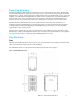
Executive Summary The Dell™ PowerEdge™ Rack Enclosures are offered in two sizes, 24U (2420) and 42U (4220). The Dell 2420 and 4220 Rack Enclosures are designed to hold and protect server, network, and data storage equipment. The Dell Rack Enclosure is a sturdy, practical design that is solidly built and delivered with Dell quality service, support, and reliability.
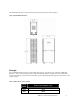
The 4220 Rack Enclosure is a 42U rack that has the following dimensions shown in Figure 2. Figure 2: Dell 4220 Rack Enclosure Strength The new Dell Rack Enclosures have increased static load capacity versus the previous generation of Dell Rack Enclosures. They have been upgraded with redesigned frame base members, stronger corner weld joints, better reinforced leveling feet, and new castor wheels made of nylon with higher impact strength over the previous version of castor wheels. Table 1.
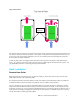
Cooling The Dell 2420 and 4220 Rack Enclosures have been designed to provide the necessary thermal environment to help reduce inefficiency at the rack level in cooling your rack mount equipment in the data center environment. When it comes to cooling in the rack environment, the two key areas that need to be addressed are airflow into the rack and management of the hot air exhaust inside the rack.
Figure 4: Rack Airflow Gap Allows Recirculation The 2420 and 4220 are designed to prevent the return path for hot air exhaust from traveling to the front of the rack. The sides are sealed with side closeout panels. These panels overlap the front mounting rails such that even if you choose to move the front mounting rails back up to 2-1/4”, the seal between the front mounting rail and the side closeout panels can still be maintained.
When you’re ready to remove the rack from the pallet, check the leveling feet inside the rack and be sure they are in the fully-retracted or upward position and not down towards the pallet before unbolting the rack from the pallet. The 2420 and 4220 Rack Enclosures are secured to their shipping pallet with L-brackets in the front and Z-brackets in the rear. In order to remove the rack from the pallet: follow the steps listed below. • Open the front door and pull out the ramps from under the rack frame.
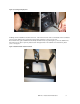
Figure 6: Leveling Feet Deployment Installing rack level stabilizers should be done next. The 4220 rack comes with a set of brackets in the rack that are used to provide stability when equipment is being loaded, unloaded, or serviced in the rack. Reach into the rack, grab a stabilizer bracket firmly with both hands, and pull straight up. Once the stabilizer has been removed, use pliers to push the plastic fastener through the hole in the stabilizer and discard these plastic pieces. See Figure 7.
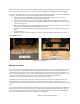
As shown in the installation guide included in the hardware kit, line up the stabilizers in front of the rack, then secure the stabilizers to the rack using the hardware provided in the kit. See Figure 8. Figure 8: Stabilizer Installation Coupling Racks 4220 Rack Enclosures can be coupled using an interconnect accessory kit that can be purchased with the Dell Rack Enclosure. This kit can be used to couple the 4220 to another 4220 or to a previous generation Dell 4210 Rack Enclosure.
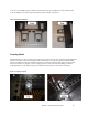
Power Distribution Unit (PDU) Installation Rear Mount PDUs The Dell 4220 and 2420 Rack Enclosures have provisions to mount a larger variety of Power Distribution Units (PDUs) than the legacy rack enclosures. The biggest change is the addition of the PDU trays in the rear of the rack enclosure. These are designed to mount different varieties of rear mount, full-height, and half-height PDUs from various suppliers. PDUs with the button mounting design are now readily accepted.
Figure 11: Rail Clearance to PDUs Zero U Mount PDUs The 2420 and 4220 racks still support the Dell zero U mount PDUs that mount in the sides of the rack. For PDUs with detachable input cables, simply mount the PDU from the side of the rack and then plug the cable in and route it back into the rack through the opening between the rear mounting rail and the PDU tray. Plugging cables into PDUs of this design is easiest when the user has ready access to the sides of the rack. See Figure 12. Dell Inc.
Figure 12: Zero U Mount PDUs In order to install Zero U mount PDUs with hardwired cables and connectors that are too large to fit through the gap between the rear mounting rail and the PDU trays, follow these steps for mounting: 1. Insert the PDU through the gap between the rear mounting rail and the PDU tray. Installation should be from the inside of the rack. 2. From the side of the rack, snap the PDU tray into the mounting rail.
Figure 13: Installing Hardwired Zero U PDUs Cabling The Dell 2420 and 4220 Rack Enclosures have been designed with improved internal and external cable management features. Internal Cable Management The Dell 2420 and 4220 Rack Enclosures are 2.7” (70mm) deeper than the older Dell 4210 Rack Enclosures. This extra room allows the user more space for cabling inside the rack. There are a few different cabling scenarios with the 2420/4220 racks depending on where PDUs are mounted.
Figure 14: Internal Cable Management Cable Rings Cabling is different when using rear-mount PDUs placed in PDU trays. If the user plans to separate power and data on opposite sides of the rack, then PDUs would be mounted in one PDU tray and the data cables can be routed into the PDU tray on the opposite side. When using Dell Cable Management Arms (CMAs), all cables will exit the CMA on one side.
Figure 15: Cabling with Rear-mount PDUs Another option is to mount one PDU on each side of the rack. This involves a similar routing schemes to the one used above. If there is no need for redundant power hookups, then this scenario is cleanest with no cable crossover point. The system CMAs can be balanced, half mounted on one side, and the other half mounted on the other side of the rack. All cables can then be routed up or down their respective sides. See Figure 16.
External cable management improvements include the enlarging and farthest-possible rear placement of top and bottom exits to accommodate a high density cable bundle. In addition, the removable tail bars at top and bottom make routing cables through the cable egress points much easier.