Benutzerhandbuch für Dell EMC PowerEdge RAID-Controller 9 H330, H730 und H830 Vorschriftenmodell: UCPA-901, UCPB-900, UCSA-901, UCSB-900, UCSE-900, and UCPE-900
Anmerkungen, Vorsichtshinweise und Warnungen ANMERKUNG: Eine ANMERKUNG macht auf wichtige Informationen aufmerksam, mit denen Sie Ihr Produkt besser einsetzen können. VORSICHT: Ein VORSICHTSHINWEIS macht darauf aufmerksam, dass bei Nichtbefolgung von Anweisungen eine Beschädigung der Hardware oder ein Verlust von Daten droht, und zeigt auf, wie derartige Probleme vermieden werden können.
Inhaltsverzeichnis 1 Übersicht....................................................................................................................................................... 9 Unterstützte Betriebssysteme........................................................................................................................................ 13 Technische Daten zur PERC-Karte................................................................................................................................
Cache-Leserichtlinien virtueller Laufwerke................................................................................................................... 31 Neukonfiguration von virtuellen Festplatten................................................................................................................. 31 Fehlertoleranz...................................................................................................................................................................
Einrichten von virtuellen Festplatten............................................................................................................................. 67 Menüoptionen im BIOS-Konfigurationsdienstprogramm............................................................................................ 69 Verwaltung virtueller Laufwerke.............................................................................................................................. 69 Maßnahmen für virtuelle Festplatten.....
Aufrufen des UEFI-Konfigurationsdienstprogramms...................................................................................................89 Beenden des UEFI-Konfigurationsdienstprogramms.................................................................................................. 90 Navigieren zum Dell PERC 9-Konfigurationsdienstprogramm................................................................................... 90 Konfigurationsverwaltung.................................................
9 Fehlerbehebung......................................................................................................................................... 104 Adapter At Baseport Not Responding Error Message (Fehlermeldung "Adapter am Baseport reagiert nicht").............................................................................................................................................................................. 104 BIOS Disabled Error Message (Fehlermeldung "BIOS deaktiviert")............
PERC-Karte wird im Geräte-Manager nicht angezeigt........................................................................................ 114 Probleme mit physischen Festplatten...........................................................................................................................114 Physische Festplatte in fehlerhaftem Zustand......................................................................................................
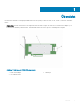
1 Übersicht Die Karten des Dell EMC PowerEdge Expandable RAID-Controller (PERC) 9 umfassen H330-, H730-, H730P-, H730P MX- und H830Karten. • PERC H330: Die PERC H330-Karte ist eine allgemeine Karte für RAID-Lösungen. Die Karte ist in Formfaktoren für Adapter- (Low Profile und volle Bauhöhe), Mini Monolithic- und Mini-Blade-Karten für interne Speicher- und Bandgeräte verfügbar. Abbildung 1.
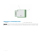
Abbildung 2. Funktionen der PERC H330 Mini Monolithic-Karte 1 • Kühlkörper 2 PERC H330 Mini Monolithic-Karte PERC H730: Die PERC H730 ist eine Karte für RAID-Lösungen, die aus mindestens 1 GB nicht-flüchtigen Cache (NVC) besteht und in Formfaktoren für Adapter- (Low-Profile und Full Height), Mini Monolithic- und Mini Blade-Karten für interne Speichergeräte verfügbar ist.
Abbildung 3. Funktionen der PERC H730-Adapterkarte 1 PERC H730-Karte 2 Kühlkörper 3 Akkukabel 4 Akkuhalterung 5 SAS-Kabelanschluss Abbildung 4.
3 • Akkukabel 4 Akkuhalterung PERC H730P MX: Die PERC H730P MX-Karte ist eine MX7000-Karte für RAID-Lösungen, bestehend aus 8 GB nicht-flüchtigem Cache für die interne Verwaltung der Laufwerke. Abbildung 5. Funktionen der PERC H730P MX-Adapterkarte • 1 Kühlkörper 2 Akkufach 3 Batteriekabelanschluss 4 Entriegelungshebel 5 SAS-Kabelanschluss PERC H830: Die PERC H830-Karte ähnelt der H730P-Lösung, unterstützt jedoch auch externen Speicher.
• PERC H830: Die PERC H830-Karte ähnelt der H730P-Lösung, unterstützt jedoch auch externen Speicher. Die PERC H830-Karte ist lediglich im Formfaktor für Adapterkarten (Low Profile und volle Bauhöhe) verfügbar. Abbildung 7.
• Linux – Red Hat Enterprise Linux Version 6.5 (64 Bit) – Red Hat Enterprise Linux 6.5 for HPC Compute Node – Red Hat Enterprise Linux Version 6.6 – Red Hat Enterprise Linux Version 6.7 – Red Hat Enterprise Linux Version 6.8 – Red Hat Enterprise Linux Version 7 – Red Hat Enterprise Linux Version 7.1 – Red Hat Enterprise Linux Version 7.
Funktion PERC H330 PERC H730 PERC H730P PERC H730P MX PERC H830 PERC FD33xD/ FD33xS Maximale Anzahl virtueller Festplatten 16 64 64 64 240 64 Maximale Anzahl virtueller Laufwerke pro Laufwerksgruppe 16 16 16 16 16 16 Hot-Swap-Geräte unterstützt Ja Ja Ja Ja Ja Ja Hardware XOR Engine Nein Ja Ja Ja Ja Ja OnlineKapazitätserweiter ung Ja Ja Ja Ja Ja Ja Dedizierte und globale Hot-SpareFestplatten Ja Ja Ja Ja Ja Ja Treibertypen 3-Gbit/s-SATA-, 6-Gbit/s-SATA-/ SAS-
Umfassende integrierte Verwaltung (CEM) CEM (Comprehensive Embedded Management) ist eine Speicherverwaltungslösung für Dell Systeme, die Ihnen über iDRAC die effektive Überwachung der auf dem System installierten RAID- und Netzwerk-Controller ermöglicht, ohne dass ein Betriebssystem im System installiert sein muss.
2 Erste Schritte mit Ihrer PERC-Karte Die nachfolgend beschriebenen Workflows beschreiben die Verfahren für die ersten Schritten mit der PERC-Karte basierend auf Ihrer Systemkonfiguration: • Installieren des Betriebssystems und der PERC-Karte auf einem Basissystem • Installieren der PERC-Karte auf einem System mit vorinstalliertem Betriebssystem • Installieren des Betriebssystems auf einem System mit vorinstallierter PERC-Karte • Einrichten des Systems mit vorinstallierter PERC-Karte und vorinstallie
e 4 Initialisieren von virtuellen Festplatten 5 Durchführen der Hintergrundinitialisierung 6 Erstellen gesicherter virtueller Laufwerke 7 Sichern bereits bestehender virtueller Laufwerke Verwalten von Controllern durch BIOS 1 Aktivieren der Startunterstützung 2 Aktivieren der Startunterstützung für einen BIOS-aktivierten Controller 3 Aktivieren des BIOS-Stopps bei einem Fehler 4 Auto Import aktivieren 4 Installieren Sie das Betriebssystem.
e 5 2 Überprüfen der Datenkonsistenz 3 Gesichertes Cache verwalten 4 Initialisieren von virtuellen Festplatten 5 Durchführen der Hintergrundinitialisierung 6 Erstellen gesicherter virtueller Laufwerke 7 Sichern bereits bestehender virtueller Laufwerke Verwalten von Controllern durch BIOS 1 Aktivieren der Startunterstützung 2 Aktivieren der Startunterstützung für einen BIOS-aktivierten Controller 3 Aktivieren des BIOS-Stopps bei einem Fehler 4 Auto Import aktivieren Außerdem können Sie
4 Auto Import aktivieren 2 Installieren Sie das Betriebssystem. Weitere Informationen finden Sie in der Dokumentation zu Ihrem Betriebssystem. 3 Installieren Sie die Betriebssystemtreiber für PERC 9. 4 • Installieren Sie Windows-Treiber, wenn es sich bei Ihrem Betriebssystem um Windows handelt. Weitere Informationen finden Sie unter Installation von Windows-Treibern. • Installieren Sie Linux-Treiber, wenn es sich bei Ihrem Betriebssystem um Linux handelt.
Konfigurieren von Einstellungen für eine ausgetauschte PERC-Karte auf einem System mit vorinstalliertem Betriebssystem 1 Tauschen Sie die vorhandene PERC-Karte durch eine neue aus und installieren Sie die PERC 9-Karte im System. Weitere Informationen finden Sie unter Bereitstellen der PERC-Karte. 2 Laden Sie die PERC 9-Treiber von der Dell Support-Website herunter. Weitere Informationen finden Sie unter Dell.com/support/home.
3 Funktionen Karten der PowerEdge RAID Controller (PERC) 9-Serie unterstützen die folgenden Funktionen: • • • • • • • Erweiterte Neuerstellungspriorisierung Unterstützung von 240 virtuellen Festplatten für H830 Personality-Modusverwaltung Sichere Firmware-Aktualisierung Verbesserte RAID 10-Konfiguration 4-KB-Sektor-Laufwerke 1-MB-E/A-Unterstützung für H730-, H730P-, H730P MX- und H830-Controller ANMERKUNG: Die 1 MB E/A-Funktion muss aktiviert sein.
eines Kabels oder Gehäuseverwaltungsmoduls (Enclosure Management Module, EMM) tolerieren, indem er den verbleibenden Pfad nutzt. Wenn redundante Pfade vorhanden sind, gleicht der Controller die E/A-Belastung für beide Pfade zu jedem Laufwerk automatisch aus. Der Lastausgleich erhöht den Datendurchsatz zu den in den Speichergehäusen befindlichen virtuellen Laufwerken und wird automatisch eingeschaltet, wenn redundante Pfade erkannt werden.
Abbildung 8. PERC H830-Kartenanschlüsse Informationen zum vereinheitlichten Modus finden Sie in der Dokumentation zum Gehäuse, die mit dem System ausgeliefert wurde. 2 Um mehrere Gehäuse hinzuzufügen, verkabeln Sie beide Ausgang-Anschlüsse des ersten Gehäuses mit beiden Eingang-Anschlüssen des nächsten Gehäuses. Nachdem Sie die Hardware eingerichtet haben, erkennt der Controller die redundanten Pfade und verwendet sie automatisch, um die E/A-Last auszugleichen.
Unterstützung von 240 virtuellen Festplatten für H830 Im Rahmen der Unterstützung für die automatische Konfiguration aller mit RAID 0 konfigurierten physischen Laufwerke unterstützt H830 240 virtuelle Laufwerke. Die Anzahl der unterstützten virtuellen Festplatten auf den H730 und H730P-Karten ist 64. PERC 9-Personality-Verwaltung Karten der PERC 9-Reihe unterstützen zwei Personality-Modi. • RAID-Modus: Der RAID-Modus wird häufig verwendet und die Controller werden meistens ab Werk im RAID-Modus geliefert.
Energieverwaltung physischer Laufwerke Die Energieverwaltung physischer Laufwerke ist eine Energiesparfunktion der PERC 9-Karten. Dank dieser Funktion lässt sich das Spindown für Laufwerke auf der Grundlage von Laufwerkskonfiguration und E/A-Aktivität durchführen. Die Funktion wird auf allen rotierenden SAS- und SATA-Laufwerken unterstützt und schließt nicht konfigurierte Laufwerke, konfigurierte Laufwerke und Ersatzlaufwerke ein.
Vollinitialisierung Bei der Vollinitialisierung eines virtuellen Laufwerk werden alle Blöcke überschrieben und alle bereits auf der virtuellen Laufwerk befindlichen Daten gelöscht. Nach einer Vollinitialisierung eines virtuellen Laufwerks muss keine Hintergrundinitialisierung des Laufwerks mehr durchgeführt werden. Eine Vollinitialisierung kann nach dem Erstellen eines virtuellen Laufwerks durchgeführt werden. Bei der Vollinitialisierung kann der Host nicht auf das virtuelle Laufwerk zugreifen.
Die Konsistenzprüfung und die Hintergrundinitialisierung beheben beide Paritätsfehler. Die Konsistenzprüfung gibt allerdings im Gegensatz zur Hintergrundinitialisierung auch Ereignisbenachrichtigungen zu inkonsistenten Daten aus. Die Konsistenzprüfung lässt sich manuell starten, die Hintergrundinitialisierung nicht. Laufwerks-Roaming Laufwerk-Roaming bedeutet die Verschiebung der physischen Laufwerke auf demselben Controller von einem Kabelanschluss oder Einsteckplatz der Rückwandplatine zu einem anderen.
Tabelle 2. FastPath-Eignung über unterstützte RAID-Level Lesen Schreiben RAID 0 RAID 1 RAID 5 RAID 6 RAID 10 Ja Ja Ja Ja Ja (Optimal und herabgesetzt) (Optimal und herabgesetzt) (Optimal und herabgesetzt) Ja Nein Nein Ja (Optimal) Ja Migration virtueller Laufwerke Die PERC 9-Karte unterstützt die Migration virtueller Festplatten von einem Controller zum anderen, ohne den Ziel-Controller offline zu nehmen.
Cache-Schreibrichtlinien virtueller Laufwerke Die Cache-Schreibrichtlinie einer virtuellen Festplatte entscheidet, auf welche Weise der Controller Daten auf die virtuelle Festplatte schreibt. Tabelle 3. Cache-Schreibrichtlinien Funktion Beschreibung Rückschreiben Der Controller sendet ein Abschlusssignal der Datenübertragung an den Host, wenn der Controller-Cache alle Daten in einer Transaktion erhalten hat.
Cache-Leserichtlinien virtueller Laufwerke Das Leseverfahren eines virtuellen Laufwerks entscheidet, auf welche Weise der Controller Daten von diesem Laufwerk liest. Tabelle 4. Leserichtlinien Funktion Beschreibung Vorauslesen Ermöglicht dem Controller, die angeforderten Daten sequenziell vorauszulesen und die zusätzlichen Daten in der Annahme im Cache zu speichern, dass sie bald benötigt werden.
ANMERKUNG: RLM wird nur auf dem H730- und dem H830-Controller unterstützt und nicht auf dem H330-Controller.
In der folgenden Tabelle finden Sie eine Auflistung der RLM- bzw. OCE-Möglichkeiten.
Tabelle 5. RAID-Level-Migration Quell-RAID-Level Ziel-RAID-Stufe Anzahl physischer Laufwerke (am Anfang) Anzahl physischer Laufwerke (am Schluss) Kapazitätserweiteru Beschreibung ng möglich RAID 0 RAID 0 1 2 oder mehr Ja Erhöht die Kapazität durch Hinzufügen von Laufwerken. RAID 0 RAID 1 1 2 Nein Konvertiert ein nicht redundantes virtuelles Laufwerk in ein gespiegeltes virtuelles Laufwerk durch Hinzufügen eines Laufwerks.
Quell-RAID-Level Ziel-RAID-Stufe Anzahl physischer Laufwerke (am Anfang) Anzahl physischer Laufwerke (am Schluss) Kapazitätserweiteru Beschreibung ng möglich Paritätsdaten hinzugefügt werden. RAID-6 RAID 0 4 oder mehr 4 oder mehr Ja Konvertierung in ein nicht redundantes virtuelles Laufwerk und Rückgewinnung von für verteilte Paritätsdaten verwendetem Speicherplatz.
Ein SMART-Ausfall wird auch als vorhersehbarer Ausfall bezeichnet. Es gibt viele Faktoren im Zusammenhang mit vorhersehbaren Fehlern physischer Laufwerke, z. B. Lagerungsfehler, ein defekter Schreib-/Lesekopf und Veränderungen der Hochfahrrate. Außerdem gibt es Faktoren hinsichtlich Schreib-/Leseoberflächenfehler, wie z. B. die Suchfehlerrate und überhöhte beschädigte Sektoren. ANMERKUNG: Genaue Informationen zur SCSI-Schnittstelle finden Sie in t10.org und zur SATA-Schnittstelle in t13.org.
Erkennung eines Ausfalls eines physischen Laufwerks Fehlerhafte physische Laufwerke werden erkannt und die Neuerstellung wird auf in den gleichen Steckplatz eingesetzten neuen Laufwerken automatisch gestartet. Die automatische Neuerstellung kann auch mithilfe von Ersatzlaufwerken durchgeführt werden. Wenn Sie die Ersatzlaufwerke konfiguriert haben, versuchen die Controller automatisch, sie zum Wiederaufbau des fehlerhaften physischen Laufwerks zu verwenden.
ANMERKUNG: Der Controller setzt ein Ersatzlaufwerk nur dann automatisch zurück, wenn das fehlerhafte Laufwerk durch ein neues im selben Steckplatz ersetzt wird. Wenn das neue Laufwerk nicht im selben Steckplatz eingesetzt wird, muss ein manueller Mitgliederaustausch-Vorgang durchgeführt werden, damit das zuvor eingesetzte Ersatzlaufwerk zurückgesetzt werden kann. ANMERKUNG: Ein Mitgliederaustausch-Vorgang verursacht meist eine temporäre Beeinträchtigung der Laufwerksleistung.
Bedingungen für den Austausch des Akkus Der PERC-Akku weist den Status Failed (Fehlerhaft) auf, wenn der Status oder Zustand des Akkus als defekt eingestuft wird. Wenn der Akku als fehlerhaft eingestuft wird, führt die Firmware bei nachfolgenden Systemstarts Lernzyklen durch, bis der Akku ausgetauscht wird. Nach dem Austausch des Akkus ändert sich der Modus des virtuellen Laufwerks zu Write Back (.
4 Bereitstellen der PERC-Karte VORSICHT: Manche Reparaturarbeiten dürfen nur von qualifizierten Servicetechnikern durchgeführt werden. Maßnahmen zur Fehlerbehebung oder einfache Reparaturen sollten Sie nur dann selbst durchführen, wenn dies laut Produktdokumentation genehmigt ist, oder wenn Sie vom Team des Online- oder Telefonsupports dazu aufgefordert werden. Schäden durch nicht von Dell genehmigte Wartungsarbeiten werden durch die Garantie nicht abgedeckt.
• Einsetzen der PERC FD33xD-Karte Entfernen der PERC H730P MX-Adapterkarte VORSICHT: Manche Reparaturarbeiten dürfen nur von qualifizierten Servicetechnikern durchgeführt werden. Maßnahmen zur Fehlerbehebung oder einfache Reparaturen sollten Sie nur dann selbst durchführen, wenn dies laut Produktdokumentation genehmigt ist, oder wenn Sie vom Team des Online- oder Telefonsupports dazu aufgefordert werden. Schäden durch nicht von Dell genehmigte Wartungsarbeiten werden durch die Garantie nicht abgedeckt.
Abbildung 9. Entfernen und Installieren der PERC H730P MX-Adapterkarte 1 Kerbe der Halterung (3) 2 Entriegelungshebel 3 Kartenhalterung 4 Laschen am System 5 Systemgehäuse 6 Kartenanschluss auf der Systemplatine 7 PERC-Kartenanschluss Installieren der PERC H730P MX-Adapterkarte VORSICHT: Manche Reparaturarbeiten dürfen nur von qualifizierten Servicetechnikern durchgeführt werden.
ANMERKUNG: Achten Sie darauf, das Kabel entsprechend den Anschlusskennzeichnungen am Kabel zu verbinden. Bei vertauschten Anschlüssen funktioniert das Kabel nicht richtig. 7 Führen Sie das SAS-Datenkabel durch die Klemme an der Karte und durch den Kabelkanal auf der Innenseite des Gehäuses. 8 Verbinden Sie den Stecker mit der Aufschrift „BP SAS“ mit dem Anschluss „SAS A“ auf der Rückwandplatine und den Stecker mit der Aufschrift „CTRL SAS“ mit dem SAS-Kabelanschluss auf der Controllerkarte.
Abbildung 10. Entfernen und Installieren der PERC 9-Karte 1 Batteriekabelstecker 2 PERC 9-Karte 3 SAS-Kabel (2) 4 SAS-Datenkabelanschlüsse (2) 5 Kartenanschluss auf der Systemplatine 6 PERC-Kartenanschluss Einsetzen des PERC 9-Adapters VORSICHT: Manche Reparaturarbeiten dürfen nur von qualifizierten Servicetechnikern durchgeführt werden.
8 Verbinden Sie den Stecker mit der Aufschrift „SAS A“ mit dem Anschluss „SAS A“ auf der Rückwandplatine und den Stecker mit der Aufschrift „SAS B“ mit dem Anschluss „SAS B“ auf der Rückwandplatine. 9 Schließen Sie das System. 10 Schließen Sie das System wieder an die Steckdose an und schalten Sie das System sowie alle angeschlossenen Peripheriegeräte ein.
Abbildung 11. Entfernen und Installieren der HBA330-Mini-Monolithic-Karte 1 Speichercontrollerkabel 2 Speichercontrollerkarte 3 Halterung der Speichercontrollerkarte 4 Rückhaltehaken des Speichercontrollers Austauschen des Akkus einer H730P Mini Monolithic-Karte 1 Schalten Sie das System und alle angeschlossenen Peripheriegeräte aus. Trennen Sie das System vom Stromnetz und von den Peripheriegeräten.
Abbildung 12. Entfernen der Akkuhalterung 7 1 PECR H730P Mini Monolithic-Karte 2 Akku 3 Lasche auf der Akkuhalterung (3) 4 Akkukabel Ziehen Sie den Akku aus der Akkuhalterung.
Abbildung 13. Entfernen des Akkus 1 Akkuhalterung 2 Führung an der Akkuhalterung (2) 3 Akku 4 Akkukabel 8 Richten Sie den Ersatz-Akku an den Führungen an der Akkuhalterung aus. 9 Setzen Sie den Akku wieder in die Halterung, bis der Akku einrastet. 10 Richten Sie die Laschen an der Akkuhalterung mit dem Steckplätzen am PERC 9 Mini Monolithic-Controller aus und senken Sie die Akkuhalterung ab, bis sie einrastet. 11 Schließen Sie das Akkukabel an der PERC-Karte an.
6 b Ziehen Sie die Schrauben fest, um das Kabel und die Karte auf der Systemplatine zu befestigen. Verbinden Sie den SAS-Datenkabelanschluss mit der Karte. ANMERKUNG: Achten Sie darauf, das Kabel entsprechend den Anschlusskennzeichnungen am Kabel zu verbinden. Bei vertauschten Anschlüssen funktioniert das Kabel nicht richtig. 7 Führen Sie das SAS-Datenkabel durch die Klemme an der Karte und durch den Kabelkanal auf der Innenseite des Gehäuses.
Abbildung 14. Entfernen und Installieren einer H730P Slim-Karte 1 Steg (2) 2 H730P Slim-Kartenkabelanschluss 3 Zuglasche 4 H730P Slim-Karte 5 H730P Slim-Kartenentriegelungsriegel 6 Symbol zum Sperren und Entsperren der Halterung auf der H730P Slim-Karte Wiedereinbauen des Akkus einer H730P Slim-Karte Der Akku, der an der H730P Slim-Karte befestigt ist, kann ausgetauscht werden. 1 Schalten Sie das System und alle angeschlossenen Peripheriegeräte aus.
Abbildung 15. Entfernen des Akkus 1 Schraube zum Sichern des Akkus an der H730P SlimKarte 2 Klemme zum Sichern des Akkus an der H730P SlimKarte 3 Lasche 4 H730P Slim-Karte 5 Akku 6 Akkuhalter 7 Akkukabel 8 Flexibler Kabelhalter 10 Setzen Sie den Akku in den Akkuhalter ein. 11 Drücken Sie auf die blaue Halterung in Richtung des eingefügten Akkus. 12 Befestigen Sie die Klemme, mit der der Akku und der flexible Kabelhalter an der H730P Slim-Karte befestigt werden.
5 Senken Sie die H730P Slim-Karte in das Gehäuse, bis die Schlitze auf der Karte in die Stegen auf der Seite des Gehäuses greifen. 6 Drücken Sie den Entriegelungsriegel in die Sperr-Position, um die Karte fest im Gehäuse zu sichern. Die H730P Slim-Karte stellt eine Verbindung mit dem Rückwandplatinenanschluss her. 7 Halten Sie die Zuglasche auf dem H730P Slim-Kartenkabelanschluss und führen Sie das Kabel zwischen die SpeichermodulAuswurfvorrichtungen.
Abbildung 16. Entfernen und Installieren des PERC 9 Mini Blade-Controllers 1 Festplatten-/SSD-Rückwandplatinenkabelanschluss 2 Steckplatz auf der PCIe-Erweiterungskarte/ Speichercontrollerkarte 3 Halterungen auf der PCIe-Erweiterungs-/ Speichercontrollerkartenhalterung 4 Steg (2) Wiedereinbauen des gesicherten Akkus einer PERC 9 Mini Blade-Karte Der gesicherte Akku, der an der PERC 9 Mini Blade-Karte befestigt ist, kann ersetzt werden.
Abbildung 17. Entfernen der Akkuhalterung 1 Halterung auf der Akkuhalterung 2 Akkuhalterung des gesicherten Akkus 5 Trennen Sie den Akkukabelanschluss vom Anschluss auf dem Mini Blade und heben Se die Akkuhalterung vom System weg. 6 Ziehen Sie den Akku aus der Akkuhalterung.
Abbildung 18. Entfernen des Akkus aus der Akkuhalterung 7 1 Akkuhalterung 2 Steckplatz auf der gesicherten Akkuhalterung 3 Kabel des gesicherten Akkus 4 Akku 5 Führung für den Akku auf der Akkuhalterung Richten Sie das untere Ende des Austauschakkus an der Akkuhalterung aus und drücken Sie den Akku in Richtung der Halterung, bis er einrastet. Abbildung 19.
8 3 Kabel des gesicherten Akkus 5 Führung für den Akku auf der Akkuhalterung 4 Akku Richten Sie die Akkuhalterung mit den Führungsstiften auf dem Gehäuse aus und senken Sie die Akkuhalterung ab, bis die Führungsstiften auf dem Gehäuse in die Steckplätze für die Führungsstifte auf der Akkuhalterung einrasten. Abbildung 20.
5 Richten Sie folgende Komponenten aneinander aus: a b Schraubenbohrungen auf dem PERC 9 Mini Blade-Controller mit den Abstandshaltern auf dem Systemplatinenanschluss. Steckplätze auf der PERC 9 Mini Blade-Controllerkante mit den Abstandshaltern auf der Kartenführung. 6 Senken Sie den PERC 9 Mini Blade Controller auf den Anschluss auf der Systemplatine ab.
Abbildung 21. Entfernen und Einsetzen der PERC FD33xD-Karte 1 PERC FD33xD-Karte 2 Schraube (3) 3 Griffstelle am Kabel 4 Kabelschraube (2) 5 Griffstelle an der PERC-Karte (4) 6 Anschluss am Midplane-Schnittstellenmodul 9 Schließen Sie das System. 10 Schließen Sie das System wieder an das Stromnetz an und schalten Sie das System sowie alle angeschlossenen Peripheriegeräte ein.
Abbildung 22. Entfernen des Akkus 1 PECR FD33xD-Karte 2 Akkuhalterung 3 Akkukabel 4 Akku 8 Setzen Sie die Ersatz-Akku auf den Controller. 9 Schieben Sie die Akkuhalterung in Richtung des Akkus und schieben Sie die Akkuhalterung nach vorn, bis sie einrastet. 10 Verbinden Sie die Akkukabel mit der PERC-Karte. 11 Bauen Sie die PERC-Karte wieder ein. Weitere Informationen finden Sie unter Einsetzen der PERC FD33xD-Karte. 12 Schließen Sie das System.
6 Halten Sie das Kabel an den Griffstellen und richten Sie die Führungsstifte des Kabels an den Schraubenbohrungen an der PERC-Karte aus. 7 Ziehen Sie die Schrauben an, um das Kabel an der PERC-Karte zu befestigen. 8 Schließen Sie das System. 9 Schließen Sie das System wieder an das Stromnetz an und schalten Sie das System sowie alle angeschlossenen Peripheriegeräte ein.
5 Treiberinstallation Die Dell PowerEdge RAID Controller (PERC) 9-Karten benötigen Softwaretreiber, damit Sie unter den unterstützten Betriebssystemen arbeiten. Dieses Kapitel beschreibt die Verfahren zur Installation der Treiber für die PERC 9-Karte. ANMERKUNG: Der Treiber für PERC 9 für VMware ESXi kann innerhalb des VMware ESXi-ISO-Image von der Dell Website heruntergeladen werden. Weitere Informationen finden Sie in der VMware-Dokumentation unter Dell.com/virtualizationsolutions.
Herunterladen von Treibern über das Medium "Dell Systems Service and Diagnostic Tools" So laden Sie Treiber über das Medium Service- und Diagnoseprogramm-Extras von Dell herunter: 1 Legen Sie das Medium Service- und Diagnoseprogramm-Extras von Dell ein. Der Bildschirm Willkommen beim Dell Service- und Diagnoseprogramm wird angezeigt. 2 Wählen Sie das Modell und das Betriebssystem Ihres Systems aus. 3 Klicken Sie auf Weiter. 4 Wählen Sie den benötigten Treiber aus der angezeigten Treiberliste aus.
Installation der Treiber nach der Installation von Windows Server 2008 R2 und höher Führen Sie folgende Schritte durch, um den Treiber für den RAID-Controller auf einem System zu konfigurieren, auf dem Windows bereits installiert ist: 1 Schalten Sie das System aus. 2 Installieren Sie den neuen RAID-Controller im System. Ausführliche Anweisungen zur Installation und Verkabelung des RAID-Controllers im System finden Sie unter Bereitstellen der PERCKarte. 3 Schalten Sie das System ein.
11 Wählen Sie die INF-Datei vom Treiber-Medium aus (CD, DVD oder anderes Medium). 12 Klicken Sie auf Weiter und folgen Sie den Installationsschritten im Assistenten. 13 Klicken Sie auf Fertigstellen, um den Assistenten zu beenden, und starten Sie das System neu, damit die Änderungen wirksam werden. ANMERKUNG: Zum Aktualisieren der Treiber auf Systemen, die unter Windows Server 2008 R2 und neueren Betriebssystemen ausgeführt werden, stellt Dell Aktualisierungspakete (Dell Update Package, DUPs) bereit.
6 Das BIOS-Konfigurationsdienstprogramm Das BIOS Configuration Utility (Ctrl R) (BIOS-Konfigurationsdienstprogramm [Strg R]) ist eine auf der PERC 9-Karte integrierte Speicherverwaltungsanwendung, die RAID-Festplattengruppen und virtuelle Festplatten konfiguriert und verwaltet. Strg R ist vom Betriebssystem unabhängig. ANMERKUNG: Verwenden Sie das BIOS-Konfigurationsdienstprogramm (Strg R) für die Ersteinrichtung und für die NotfallWiederherstellung.
Falls nur ein Controller vorhanden ist, wird ein Dialogfeld angezeigt, in dem Sie den Vorgang bestätigen müssen. 2 Wählen Sie zum Beenden OK aus und drücken Sie die . Sind mehrere Controller vorhanden, gelangen Sie durch Drücken von zum Bildschirm Controllerauswahl. 3 Drücken Sie erneut , um den Bildschirm zum Beenden des Programms aufzurufen. Ein Dialogfeld wird angezeigt, in dem Sie aufgefordert werden, den Vorgang zu bestätigen.
Anmerkung Bedeutung und Verwendung Beispiel nochmals drücken, um das BIOSKonfigurationsdienstprogramm ( ) zu beenden. , um mit dem Cursor in ste> einem Dialogfeld oder auf einer Seite zum nächsten Steuerelement zu wechseln. Drücken Sie die , um mit dem Cursor zum nächsten Parameter zu wechseln, den Sie ändern möchten.
Beim Definieren der virtuellen Laufwerke können Sie folgenden Parameter festlegen: • RAID-Level • Stripe-Elementgröße • Leserichtlinie • Schreibrichtlinie • Initialisierungstyp • Konfiguration des Ersatzlaufwerks ANMERKUNG: Die standardmäßige Festplatten-Cache-Richtlinie für ein virtuelles Laufwerk mit SAS-Festplatten ist deaktiviert, und die Cache-Richtlinie für ein virtuelles Laufwerk mit SATA-Festplatten ist aktiviert.
Parameter Beschreibung Read-Ahead (Vorauslesen): legt fest, dass der Controller für das aktuelle virtuelle Laufwerk Read-Ahead (Vorauslesen) verwendet. Die Funktion Read-Ahead (Vorauslesen) ermöglicht dem Controller, die angeforderten Daten sequenziell vorauszulesen und die zusätzlichen Daten in der Annahme im Cache zu speichern, dass sie bald benötigt werden. Die Funktion Kein vorausschauendes Lesen legt fest, dass der Controller für das aktuelle virtuelle Laufwerk kein Vorausschauendes Lesen verwendet.
Im linken Fensterbereich ausgewählte Menüoption Informationen im rechten Bildschirmbereich • • • Laufwerksgruppe Nr. Eigenschaften der Laufwerksgruppe Nr.: • • • • • • Virtuelle Festplatten Anzahl der virtuellen Laufwerke (VD, virtual disks) Anzahl der physischen Laufwerke (PD; physical disks) Auf den physischen Laufwerken verfügbarer Speicherplatz Anzahl der freien Segmente Anzahl der dedizierten Ersatzlaufwerke Sicherheitseigenschaft der Laufwerksgruppe Eigenschaften der Laufwerksgruppe Nr.
Im linken Fensterbereich ausgewählte Menüoption Informationen im rechten Bildschirmbereich • • • Gesamte freie Kapazität Auf den physischen Laufwerken verfügbarer Speicherplatz Anzahl der freien Segmente Anzahl der dedizierten Ersatzlaufwerke Eigenschaften der Laufwerksgruppe Nr.
Action (Aktion) Beschreibung Beibehaltenen Cache verwalten Behält den fehlerhaften Cache eines virtuellen Laufwerks bei, wenn dieses offline geschaltet oder gelöscht wird. Der fehlerhafte Cache wird beibehalten, bis Sie das virtuelle Laufwerk importieren oder den Cache löschen. Ein virtuelles Laufwerk löschen Löscht das virtuelle Laufwerk und gibt Speicherplatz zum Erstellen eines weiteren virtuellen Laufwerks frei.
Tabelle 11. Maßnahmen für physische Laufwerke Aktion Beschreibung Neu erstellen Stellt nach einem Laufwerksausfall in einem redundanten virtuellen Laufwerk (RAID-Level 1, 5, 6, 10, 50 und 60) alle Daten auf einem Austauschlaufwerk wieder her. Eine Neuerstellung eines Laufwerks erfolgt in der Regel ohne Unterbrechung der normalen Abläufe auf dem betroffenen virtuellen Laufwerk. Mitglied ersetzen Tauscht die Laufwerke im virtuellen Laufwerk mit einem anderen auszuwählenden Laufwerk aus.
Controllerverwaltung (Ctrl Mgmt) Der Bildschirm Controller Management (Ctrl Mgmt) enthält den Produktnamen, das Produktpaket, die Firmware-Version , BIOS-Version, Boot-Block-Version, Controller-ID, Sicherheitsfunktion und den Sicherheitsschlüssel. Verwenden Sie diesen Bildschirm, um Aktionen für den Controller und das BIOS durchzuführen. Sie können bestimmte Funktionen durchführen, z. B.
Fremdkonfigurationsansicht Wenn eine Fremdkonfiguration vorhanden ist, können Sie die Fremdkonfigurationsansicht wählen, um diese Konfiguration anzuzeigen. Der Bildschirm zeigt die Fremdkonfiguration so, wie sie nach dem Importieren wäre. Sie können eine Vorschau auf die Fremdkonfiguration ansehen, bevor Sie entscheiden, ob Sie sie importieren oder löschen. In manchen Fällen kann eine Fremdkonfiguration nicht importiert werden.
10 Wählen Sie bei Bedarf weitere Laufwerke aus. 11 Bewegen Sie den Cursor mit der auf das Feld Basic Settings (Grundeinstellungen). 12 Legen Sie die Größe des virtuellen Laufwerks im Feld Größe des virtuellen Laufwerks fest. Die Größe des virtuellen Laufwerks wird in GB angezeigt. 13 Drücken Sie die , um in das Feld VD Name (Name des virtuellen Laufwerks) zu wechseln, und geben Sie einen Namen für das virtuelle Laufwerk ein.
16 Nachdem Sie die Laufwerkgröße ausgewählt haben, klicken Sie OK, um die ausgewählten Einstellungen abzuschließen oder Abbrechen, um sie zu verwerfen. 17 Wählen Sie OK aus, um die Einstellungen zu übernehmen, und drücken Sie dann die , um dieses Fenster zu schließen. Oder wählen Sie Abbrechen aus, und drücken Sie die , um das Fenster zu schließen, ohne die Änderungen an den Parametern der virtuellen Laufwerke zu speichern.
Importieren oder Löschen von Fremdkonfigurationen mithilfe des Menüs zur Verwaltung virtueller Laufwerke Wenn eine Fremdkonfiguration vorhanden ist, zeigt der BIOS-Bildschirm die Meldung Foreign configuration(s) found on adapter an. Zusätzlich wird eine Fremdkonfiguration auf der rechten Seite des Bildschirms Controllerverwaltung angezeigt. Sie können mit dem Menü Verwaltung virtueller Laufwerke die vorhandene Konfiguration auf den RAID-Controller importieren oder die vorhandene Konfiguration löschen.
ANMERKUNG: Überprüfen Sie die Fremdkonfiguration auf dem Bildschirm, bevor Sie sie importieren, damit das gewünschte Ergebnis gewährleistet ist. Sie können den Bildschirm Foreign Config (Fremdkonfiguration) in folgenden Fällen zum Verwalten von Fremdkonfigurationen verwenden: • Alle physischen Laufwerke in einer Konfiguration werden entfernt und wieder eingesetzt. • Einige der physischen Laufwerke in einer Konfiguration werden entfernt und wieder eingesetzt.
ANMERKUNG: Starten Sie unmittelbar nach Abschluss der Neuerstellung eine Konsistenzprüfung, um die Datenintegrität für die virtuellen Laufwerke sicherzustellen. Weitere Informationen zur Überprüfung der Datenkonsistenz finden Sie unter Überprüfen der Datenkonsistenz. 3 Wenn die physischen Laufwerke eines nicht redundanten virtuellen Laufwerks entfernt werden, gelten die Laufwerke für den Controller als fremdkonfiguriert.
ANMERKUNG: Das Importieren einer beschädigter Spiegelung entspricht dem Importieren einer Fremdkonfiguration. Weitere Informationen finden Sie unter Importieren oder Löschen von Fremdkonfigurationen mithilfe des Menüs „VD Mgmt“ (Verwaltung virtueller Laufwerke). Das importierte virtuelle Laufwerk befindet sich im heruntergestuften Zustand, bis das fehlende Mitglied neu erstellt wurde.
1 Markieren Sie mit der Nach-unten-Taste ein verfügbares physisches Laufwerk. 2 Drücken Sie die Leertaste, um das Laufwerk auszuwählen. 3 Wiederholen Sie die Schritte 1 und 2 für jedes zu erstellende dedizierte Ersatzlaufwerk. ANMERKUNG: Neben dem/den ausgewählte(n) physische(n) Laufwerk(en) wird ein X angezeigt. • 4 Ein dediziertes Ersatzlaufwerk löschen 1 Markieren Sie mit der Nach-unten-Taste ein aktuelles Ersatzlaufwerk. 2 Drücken Sie die Leertaste, um die Auswahl des Laufwerks aufzuheben.
Löschen der Konfiguration Um die Konfiguration zu löschen, führen Sie die folgenden Schritte im BIOS-Konfigurationsdienstprogramm () durch: 1 Drücken Sie , um den Bildschirm VD Mgmt (Verwaltung virtueller Laufwerke) zu öffnen. 2 Wählen Sie den Controller mithilfe der Pfeiltasten aus. 3 Drücken Sie . Das Aktionsmenü wird angezeigt. 4 Wählen Sie Konfiguration löschen.
Eine Liste physischer Laufwerke wird angezeigt. Der Status jedes Laufwerks wird unter der Überschrift State (Status) angezeigt. 2 Markieren Sie mit der Nach-unten-Taste das physische Laufwerk, das umgewandelt werden soll. 3 Drücken Sie , um das Menü mit den verfügbaren Maßnahmen anzuzeigen. 4 Markieren Sie mit der Nach-unten-Taste entweder die Option Convert to Non-RAID (In Non-RAID umwandeln) oder Convert to RAID Capable (In RAID-fähig umwandeln).
4 Wählen Sie mit der Nach-unten-Taste in der Aktionsliste die Option Ersatzlaufwerk entfernen aus und drücken Sie die . Das physische Laufwerk wird auf den Status Bereit gesetzt. Der Status des physischen Laufwerks wird unter der Überschrift Status angezeigt. ANMERKUNG: Verwenden Sie für ein bestimmtes virtuelles Laufwerk am besten physische Laufwerke mit der gleichen Kapazität.
• Eine Konsistenzprüfung auf dem virtuellen Laufwerk Die folgende Warnmeldung wird angezeigt: The virtual disk is undergoing a background initialization process. Would you like to stop the operation and proceed with the instead? Klicken Sie auf Yes (Ja), um die Hintergrundinitialisierung anzuhalten und den angeforderten Vorgang zu starten, oder klicken Sie auf No (Nein), um die Hintergrundinitialisierung fortzusetzen.
4 Drücken Sie die , um den Cursor auf die Schaltfläche Übernehmen zu setzen. Drücken Sie dann die , um die gewählte Option zu übernehmen. Das Controller-BIOS ist aktiviert. Um das Controller-BIOS zu deaktivieren, heben Sie die Auswahl der Option Controller-BIOS aktivieren durch Drücken der Leertaste auf, wählen Sie Übernehmen und drücken Sie die .
So aktivieren Sie Auto Import: 1 Drücken Sie , um den Bildschirm Ctrl Mgmt (Controllerverwaltung) zu öffnen. 2 Drücken Sie die , um den Cursor im Feld Settings (Einstellungen) auf die Option Enable Auto Import (Auto Import aktivieren) zu setzen. 3 Drücken Sie die Leertaste, um Auto Import aktivieren auszuwählen. Neben Auto Import aktivieren wird ein X angezeigt. 4 Drücken Sie die , um den Cursor auf die Schaltfläche Apply (Übernehmen) zu setzen.
7 UEFI/HII RAID-Konfigurationsdienstprogramm Das UEFI(Unified Extensible Firmware Interface)-RAID-Konfigurationsdienstprogramm ist eine in das System-BIOS- integrierte Anwendung zur Speicherverwaltung, die zur Konfiguration und Verwaltung von RAID-Laufwerkgruppen, virtuellen Laufwerken und physischen Laufwerken eingesetzt werden kann. Dieses Dienstprogramm ist unabhängig vom Betriebssystem.
ANMERKUNG: Um weitere Informationen zu allen Optionen zu erhalten, klicken Sie rechts oben im Browser auf Hilfe. Die Hilfeinformationen zu den einzelnen Optionsmenüs lassen sich auch durch Herunterscrollen zu den einzelnen Optionen anzeigen. ANMERKUNG: Einige Optionen im UEFI RAID-Konfigurationsdienstprogramm sind nur dann vorhanden, wenn der Controller die entsprechende Funktion unterstützt. Falls die Funktion in der bestehenden Konfiguration unterstützt wird, kann die Option auch grau unterlegt sein.
6 Um die physischen Festplatten auszuwählen, aus denen die virtuellen Festplatten erstellt wurden, klicken Sie auf Select Physical Disks (Physische Festplatten auswählen). Diese Option wird angezeigt, wenn Sie Unconfigured Capacity (Nicht konfigurierte Kapazität) als physische Festplattenkapazität ausgewählt haben. 7 Um Festplattengruppen auszuwählen, aus denen die virtuellen Festplatten erstellt wurden, klicken Sie auf Select Disk Group(Festplattengruppe auswählen).
3 Wählen Sie die physische Festplatte, die in eine RAID-fähige Festplatte konvertiert werden soll. 4 Klicken Sie auf OK. Es wird ein Bildschirm angezeigt, in dem Sie gefragt werden, ob Sie den Vorgang wirklich durchführen möchten. 5 Klicken Sie auf Yes (Ja), um fortzufahren. Konvertieren physischer Festplatten in Non-RAID-Festplatten 1 Rufen Sie das Dell PERC 9-Konfigurationsdienstprogramm auf. Siehe Navigieren zum PERC 9-Konfigurationsdienstprogramm.
Löschen von vorhandenen Konfigurationen auf einem RAIDController 1 Rufen Sie das Dell PERC 9-Konfigurationsdienstprogramm auf. Siehe Navigieren zum PERC 9-Konfigurationsdienstprogramm. 2 Klicken Sie auf Configuration Management (Konfigurationsverwaltung) > Clear Configuration (Konfiguration löschen). 3 Klicken Sie auf OK. Es wird ein Bildschirm angezeigt, in dem Sie gefragt werden, ob Sie den Vorgang wirklich durchführen möchten. 4 Klicken Sie auf Yes (Ja), um fortzufahren.
Speichern des Debugprotokolls 1 Rufen Sie das Dell PERC 9-Konfigurationsdienstprogramm auf. Siehe Navigieren zum PERC 9-Konfigurationsdienstprogramm. 2 Klicken Sie auf Controller Management (Kontrollerverwaltung) > Save Debug Log (Debugprotokoll speichern). 3 Wählen Sie das Dateisystem aus. 4 Wählen Sie das Verzeichnis aus, in dem die Protokolldatei mit den Controllerereignissen gespeichert werden soll.
3 Klicken Sie auf OK. Es wird ein Bildschirm angezeigt, in dem Sie gefragt werden, ob Sie den Vorgang wirklich durchführen möchten. 4 Klicken Sie auf Yes (Ja), um fortzufahren. Verwaltung virtueller Laufwerke Anzeigen der Eigenschaften von virtuellen Festplatten 1 2 Rufen Sie das Dell PERC 9-Konfigurationsdienstprogramm auf. Siehe Navigieren zum PERC 9-Konfigurationsdienstprogramm. Klicken Sie auf Virtual Disk Management (Verwaltung von virtuellen Festplatten).
3 Klicken Sie auf das physische Laufwerk, um die Eigenschaften anzuzeigen. Sie können die folgenden Eigenschaften des physischen Laufwerks anzeigen: Option Beschreibung Operation Zeigt die Liste der Vorgänge an, die Sie auf dem ausgewählten physischen Laufwerk durchführen können.
Alle physischen Festplatten, die der virtuellen Festplatte zugeordnet sind, werden angezeigt. Controllerverwaltung (Ctrl Mgmt) Der Bildschirm Controller Management (Ctrl Mgmt) enthält den Produktnamen, das Produktpaket, die Firmware-Version , BIOS-Version, Boot-Block-Version, Controller-ID, Sicherheitsfunktion und den Sicherheitsschlüssel. Verwenden Sie diesen Bildschirm, um Aktionen für den Controller und das BIOS durchzuführen. Sie können bestimmte Funktionen durchführen, z. B.
configuration. If you wish to use them at a later time, they will have to be imported. If you believe these virtual disks should be present, please power off your system and check your cables to ensure all disks are present. Press any key to continue, or 'C' to load the configuration utility. The cache contains dirty data, but some virtual disks are missing or will go offline, so the cached data cannot be written to disk.
8 Sicherheitsschlüssel und RAID-Verwaltung ANMERKUNG: Die H330 PERC-Karte unterstützt keine Sicherheitsschlüssel und RAID-Verwaltungsfunktionen. Themen: • Implementierung des Sicherheitsschlüssels • Sicherheitsschlüsselverwaltung im BIOS-Konfigurationsdienstprogramm Implementierung des Sicherheitsschlüssels Die Dell PowerEdge RAID-Controller(PERC) 9-Karte unterstützt selbstverschlüsselnde Laufwerke (Self-Encrypting Disks, SED) zum Schutz vor Datenverlust oder Diebstahl von SEDs.
Local Key Management Sie können Local Key Management (LKM) zum Generieren der Schlüssel-ID und der Passphrase verwenden, die zum Sichern des virtuellen Laufwerks erforderlich sind. Mit diesem Sicherheitsmodus können Sie virtuelle Laufwerke sichern, Sicherheitsschlüssel ändern und gespeicherte Fremdkonfigurationen verwalten. ANMERKUNG: Unter LKM werden Sie aufgefordert, einen Kennsatz einzugeben, wenn Sie den Schlüssel erzeugen.
3 Drücken Sie , um die möglichen Maßnahmen anzuzeigen. 4 Markieren Sie mithilfe der Pfeiltasten die Sicherheitsschlüsselverwaltung. 5 Wählen Sie Schlüssel ändern und drücken Sie die . Der Bildschirm Sicherheitsschlüssel ändern wird angezeigt. Der Curser steht auf Sicherheitsschlüsselkennung. 6 Geben Sie eine Kennung für den Sicherheitsschlüssel ein. 7 Drücken Sie die , um einen neuen Kennsatz einzugeben.
Sichern von bereits bestehenden virtuellen Festplatten Wenn auf einem Controller ein ungesichertes virtuelles Laufwerk erstellt wurde, können Sie das virtuelle Laufwerk unter folgenden Voraussetzungen sichern: • Auf dem Controller ist ein Sicherheitsschlüssel vorhanden. • Alle physischen Laufwerke im virtuellen Laufwerk sind SEDs.
ANMERKUNG: Zum Clear (Löschen) müssen Sie das Secure Erase (Sichere Löschen) von Fremdkonfigurationen durchführen, die mit einem anderen Sicherheitsschlüssel gesichert sind. 5 Wenn Sie Import (Importieren) der Fremdkonfiguration wählen, wird der Bildschirm Secure Foreign Import (Sicherer Fremdimport) angezeigt. ANMERKUNG: Die Schlüsselkennung für den verwendeten Kennsatz zum Sichern der gesicherten virtuellen Fremdfestlaufwerke wird unter der Option Gesicherte Laufwerke angezeigt.
9 Fehlerbehebung Um Hilfe zu Ihren Dell PowerEdge RAID-Controller (PERC) 9-Karten zu erhalten, können Sie sich an einen Mitarbeiter des technischen Kundendienstes von Dell wenden oder auf Dell.com/support zugreifen.
BIOS-Konfigurationsdienstprogramm – Fehlermeldungen Das ROM (Nur-Lesen-Speicher) des Controller-BIOS bietet Int 13h-Funktionalität (Laufwerk-E/A) für die virtuellen Laufwerke, die mit dem Controller verbunden sind. Sie können von den physischen Laufwerken aus starten oder darauf zugreifen, ohne einen Treiber zu benötigen. Discovery Error Message (Fehlermeldung "Ermittlungsfehler") Fehlermeldung: A discovery error has occurred, please power cycle the system and all the enclosures attached to this system.
Previous Configuration Of Disks Removed Error Message (Fehlermeldung "Vorherige Festplattenkonfiguration wurde entfernt") Error Message: All of the disks from your previous configuration are gone. If this is an unexpected message, then please power off your system and check your cables to ensure all disks are present. Press any key to continue, or press to load the configuration utility. Mögliche Ursache: Einige konfigurierte Laufwerke wurden aus dem System entfernt.
Mögliche Ursache: Der Controller behält den fehlerhaften Cache eines virtuellen Laufwerks bei, wenn dieses offline geht oder aufgrund fehlender physischer Laufwerke gelöscht wird. Diese Meldung zeigt an, dass einige konfigurierte Laufwerke entfernt wurden. Wenn die Laufwerke nicht entfernt wurden, ist der Zugriff aus anderen Gründen nicht mehr möglich. Möglicherweise sind die SAS-Kabel des Systems nicht ordnungsgemäß angeschlossen.
Offline Or Missing Virtual Drives With Preserved Cache Error Message (Fehlermeldung "Virtuelle Festplatten mit beibehaltenem Cache fehlen oder sind offline") Fehlermeldung: There are offline or missing virtual drives with preserved cache. Please check the cables and ensure that all drives are present. Press any key to enter the configuration utility.
Virtual Disks Partially Degraded Error Message (Fehlermeldung "Teilweise funktionsbeeinträchtigte virtuelle Festplatten") Fehlermeldung: x Virtual Disk(s) Partially Degraded, where x is the number of virtual disks partially degraded. Mögliche Ursache: Diese Warnung wird angezeigt, wenn das BIOS den Ausfall eines einzelnen Laufwerks in einer RAID 6- oder RAID 60-Konfiguration erkennt. Korrekturmaßnahme Damit das Problem behoben werden kann, müssen Sie ermitteln, weshalb das Laufwerk nicht erkannt wird.
Foreign Configuration Found Error Message (Fehlermeldung "Fremdkonfiguration gefunden") Fehlermeldung: Foreign configuration(s) found on adapter. Press any key to continue, or ’C’ to load the configuration utility or ’F’ to import foreign configuration(s) and continue. Mögliche Ursache: Wenn die Firmware eines Controllers ein physisches Laufwerk mit bestehenden Fremdmetadaten erkennt, kennzeichnet sie das physische Laufwerk als Fremd und erzeugt eine Meldung, dass ein Fremdlaufwerk erkannt wurde.
Korrekturmaßnahme Zum Entfernen der Fremdkonfiguration können Sie das BIOS-Konfigurationsdienstprogramm ( ) : verwenden. Invalid SAS Topology Detected Error Message (Fehlermeldung "Ungültige SAS-Topologie festgestellt") Fehlermeldung: Invalid SAS topology detected. Please check your cable configurations, repair the problem, and restart your system. Mögliche Ursache: Die SAS-Kabel des Systems sind nicht ordnungsgemäß angeschlossen.
Extra Enclosure Error Message (Fehlermeldung "Zusätzliches Gehäuse") Fehlermeldung: There are X enclosures connected to connector Y, but only maximum of 4 enclosures can be connected to a single SAS connector. Please remove the extra enclosures then restart your system. Mögliche Ursache: Diese Meldung wird angezeigt, wenn das BIOS erkennt, dass mehr als vier Gehäuse an einen einzigen SASAnschluss angeschlossen sind.
Verwenden Sie das BIOS-Konfigurationsdienstprogramm ( ), um die virtuellen Laufwerke zu importieren oder den beibehaltenen Cache zu verwerfen. Wählen Sie im Menü Verwaltung virtueller Laufwerke die Option Beibehaltenen Cache verwalten, und befolgen Sie die Anweisungen auf dem Bildschirm.
Das sichere Löschen (Secure Erase) kann nur auf verschlüsselungsfähigen Laufwerken durchgeführt werden, sofern diese keine Ersatzlaufwerke und nicht (als Teil eines virtuellen Laufwerks) konfiguriert sind. Stellen Sie sicher, dass diese Bedingungen erfüllt sind und lesen Sie dazu Sicheres Löschen. Allgemeine Probleme PERC-Karte weist im Geräte-Manager gelbes Warnsymbol auf Problem: Das Gerät wird im Geräte-Manager angezeigt, ist aber mit einem gelben Warnsymbol versehen (Ausrufezeichen).
Physisches Laufwerk wird als blockiert angezeigt Problem: Eines oder mehrere physische Laufwerke werden als Blocked (Blockiert) angezeigt und können nicht konfiguriert werden. Korrekturmaßnahme Aktualisieren Sie die PERC-Karten mit der neuesten Firmware, die auf www.dell.com/support erhältlich ist. Bauen : Sie das Laufwerk wieder ein und stellen Sie sicher, dass Sie das blockierte Laufwerk nicht verwenden.
Virtuelle Festplatte fällt während der Neuerstellung mithilfe einer globalen Hot-Spare-Festplatte aus Problem: A virtual disk fails during rebuild while using a global hot spare. Beschreibung: Das globale Hot Spare kehrt in den Status Hotspare und die virtuelle Festplatte in den Status Failed (Fehlerhaft) zurück.
SMART-Fehler Mit SMART kann die interne Leistung aller Motoren und Köpfe sowie der Elektronik des physischen Laufwerks überwacht werden, so dass vorhersehbare Ausfälle des physischen Laufwerks erkannt werden können. ANMERKUNG: Weitere Informationen zu SMART-Fehlerberichten, die Hardwareausfälle anzeigen können, finden Sie in der Dokumentation zur Dell OpenManage-Speicherverwaltung auf Dell.com/openmanagemanuals.
4 Stellen Sie die Sicherungskopie wieder her. Fehler beim Mitgliederaustausch ANMERKUNG: Weitere Informationen zu der Funktion Replace Member (Mitgliederaustausch) finden Sie unter dem Thema Verwenden von Mitgliederaustausch und zurücksetzbaren Ersatzlaufwerken. Quellfestplatte fällt während Mitgliederaustausch aus Problem: The source disk fails during the Replace Member operation.
Weitere Informationen über Write-Through-Cache finden Sie unter Schreibcache-Richtlinien für virtuelle Festplatten. Abgesehen von dieser Meldung hat dieses Verhalten keine Auswirkung auf den Normalbetrieb. Die CacheSchreibrichtlinie des virtuellen Laufwerks und der E/A-Durchsatz werden von dieser Meldung nicht beeinflusst. Die Cache-Richtlinieneinstellungen für das PERC SAS RAID-System bleiben unverändert.
HII-Fehlermeldungen Fehlerhafter Status der Treiber Error: One or more boot driver(s) have reported issues. Check the Driver Health Menu in Boot Manager for details. Mögliche Ursache: Diese Meldung weist möglicherweise darauf hin, dass die Kabel nicht angeschlossen sind, die Festplatten möglicherweise fehlen oder der UEFI-Treiber möglicherweise Konfigurationsänderungen erfordert.
10 Anhang: RAID-Beschreibung RAID bezeichnet eine Gruppe von mehreren unabhängigen physischen Laufwerken, die eine höhere Leistung ermöglichen, da mehr Laufwerke für das Speichern und den Zugriff auf die Daten verwendet werden. VORSICHT: Bei Ausfall eines physischen Laufwerks fällt ein virtuelles RAID 0-Laufwerk aus, was zu Datenverlust führt. Ein RAID-Laufwerk-Subsystem bietet die folgenden Vorteile: • Verbesserte E/A-Leistung und Datenverfügbarkeit.
RAID-Level Mindestanzahl an Laufwerken Maximale Anzahl an Laufwerken 5 3 32 6 4 32 10 4 192 50 6 192 60 8 192 RAID-Terminologie Festplatten-Striping Beim Laufwerk-Striping können Sie Daten über mehrere physische Laufwerke hinweg schreiben, anstatt nur ein physisches Laufwerk zu nutzen. Beim Laufwerk-Striping erfolgt eine Partitionierung des Speicherplatzes jedes physischen Laufwerks in Blöcke der Größen 64 KB, 128 KB, 256 KB, 512 KB und 1 MB.
Abbildung 25. Beispiel für Laufwerkspiegelung (RAID 1) Übergreifende RAID-Level Der Begriff „Spanning“ (ein übergreifendes Laufwerk) beschreibt, auf welche Weise die RAID-Level 10, 50 und 60 aus mehreren Sätzen grundlegender oder einfacher RAID-Level aufgebaut werden. RAID 10 ist z. B. aus mehreren Sätzen aus RAID 1-Arrays aufgebaut, wobei jeder RAID 1-Satz als Bereich (Span) gilt.
Abbildung 27. Beispiel doppelt verteilter Parität (RAID 6) ANMERKUNG: Die Parität wird auf alle Laufwerke des Arrays verteilt.
11 Wie Sie Hilfe bekommen Sie erhalten Hilfe zu Ihrem Dell Produkt, indem Sie Kontakt mit Dell aufnehmen oder ein Feedback zur Produktdokumentation schicken. Kontaktaufnahme mit Dell EMC Dell EMC stellt verschiedene Online- und telefonische Support- und Serviceoptionen bereit. Wenn Sie nicht über eine aktive Internetverbindung verfügen, können Sie Kontaktinformationen auch auf Ihrer Auftragsbestätigung, dem Lieferschein, der Rechnung oder im Dell EMC Produktkatalog finden.