Dell EMC PowerEdge RAID Controller 9 User’s Guide H330, H730, and H830 Regulatory Model: UCPA-901, UCPB-900, UCSA-901, UCSB-900, UCSE-900, and UCPE-900
Notes, cautions, and warnings NOTE: A NOTE indicates important information that helps you make better use of your product. CAUTION: A CAUTION indicates either potential damage to hardware or loss of data and tells you how to avoid the problem. WARNING: A WARNING indicates a potential for property damage, personal injury, or death. © 2017 - 2019 Dell Inc. or its subsidiaries. All rights reserved. Dell, EMC, and other trademarks are trademarks of Dell Inc. or its subsidiaries.
Contents 1 Overview........................................................................................................................................................ 9 Supported operating systems......................................................................................................................................... 13 PERC card specifications................................................................................................................................................
Reconfiguration of virtual disks......................................................................................................................................30 Fault tolerance..................................................................................................................................................................34 The SMART feature..................................................................................................................................................
BIOS Configuration Utility menu options...................................................................................................................... 65 Virtual disk management...........................................................................................................................................66 Virtual disk actions.....................................................................................................................................................
Configuration management............................................................................................................................................ 84 Creating virtual disks................................................................................................................................................. 84 Creating profile based virtual disks..........................................................................................................................
BIOS configuration utility error messages.................................................................................................................... 98 Discovery error message.......................................................................................................................................... 99 Extra enclosure error message.................................................................................................................................
Virtual disk fails rebuild using a dedicated hot spare............................................................................................108 Physical disk takes a long time to rebuild.............................................................................................................. 108 SMART errors.................................................................................................................................................................
1 Overview The Dell EMC PowerEdge Expandable RAID Controller (PERC) 9 Series of cards consist of the H330, H730, H730P, H730P MX, and H830 cards. • PERC H330: The PERC H330 is a general purpose RAID solution card. The card is available in Adapter (low profile and full height), Mini Monolithic, and Mini Blade form factors for internal storage and tape devices. Figure 1.
Figure 2. Features of PERC H330 mini monolithic card 1 • heat sink 2 PERC H330 mini monolithic card PERC H730: The PERC H730 is a RAID solution card consisting of a minimum of 1 GB Non-Volatile Cache and is available in the Adapter (low profile and full height), Mini Monolithic, and Mini Blade form factors for internal storage. Figure 3.
3 battery cable 5 SAS-cable connector 4 battery carrier Figure 4. Features of PERC H730/H730P mini monolithic card • 1 PERC H730/H730P card 2 heat sink 3 battery cable 4 battery carrier PERC H730P MX: The PERC H730P MX is an MX7000 RAID solution card consisting of 8 GB Non-Volatile Cache that manages drives internally. Figure 5.
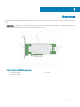
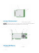
Figure 6. Features of PERC H830 adapter card • 1 external SAS-cable connector 2 PERC H830 adapter 3 heat sink 4 battery cable 5 battery carrier PERC H830: The PERC H830 is similar to the H730P solution, except that it supports external storage. The PERC H830 is only available in the Adapter (low profile and full height) form factor.
Figure 7. Features of PERC H830 adapter card 1 external SAS-cable connector 2 PERC H830 adapter 3 heat sink 4 battery cable 5 battery carrier Topics: • Supported operating systems • PERC card specifications • Management applications for PERC cards • Related documentation Supported operating systems The PERC 9 series cards support the following operating systems: • Microsoft – Windows Server 2012 – Windows Server 2012 R2 – Windows Server 2016 • VMWare – ESXi 6 – ESXi 5.
– Red Hat Enterprise Linux 6.5 for HPC Compute Node – Red Hat Enterprise Linux version 6.6 – Red Hat Enterprise Linux version 6.7 – Red Hat Enterprise Linux version 6.8 – Red Hat Enterprise Linux version 7 – Red Hat Enterprise Linux version 7.1 – Red Hat Enterprise Linux version 7.
Feature PERC H330 PERC H730 PERC H730P PERC H730P MX PERC H830 PERC FD33xD/ FD33xS Hot swap devices supported Yes Yes Yes Yes Yes Yes Hardware XOR Engine No Yes Yes Yes Yes Yes Online capacity expansion Yes Yes Yes Yes Yes Yes Dedicated and global hot spare Yes Yes Yes Yes Yes Yes Drives Types 3 Gbps SATA, 6 Gbps SATA/SAS, and 12 Gbps SAS 3 Gbps SATA, 6 3 Gbps SATA, 6 Gbps SATA/ Gbps SATA/SAS, SAS, and 12 and 12 Gbps SAS Gbps SAS 3 Gbps SATA, 6 Gbps SATA/SAS, and 12 Gbp
you to perform controller and enclosure functions for all supported RAID controllers and enclosures from a single graphical or command-line interface without using of the controller BIOS utilities. The graphical user interface (GUI) is wizard-driven with features for novice and advanced users, and detailed online help. Using the Dell OpenManage storage management application, you can protect your data by configuring data-redundancy, assigning hot spares, or rebuilding failed physical disks.
2 Getting started with your PERC card The workflows outlined below list the procedures to getting started with the PERC card, based on your system configuration: • Installing the operating system and the PERC card on a base system • Installing the PERC card on a system with the operating system pre-installed • Installing the operating system on a system with the PERC card pre-installed • Setting up the system with the PERC card and the operating system pre-installed • Configuring settings of a repl
e 6 Creating Secured Virtual Disks 7 Securing Pre-Existing Virtual Disks Managing controllers through BIOS 1 Enabling Boot Support 2 Enabling Boot Support For A BIOS-Enabled Controller 3 Enabling BIOS Stop On Error 4 Enabling Auto Import 4 Install the operating system. For more information, refer to your operating system documentation. 5 Install the operating system drivers for PERC 9. 6 • If your operating system is Windows, install the Windows drivers.
7 e 5 Securing Pre-Existing Virtual Disks Managing Controllers through BIOS 1 Enabling Boot Support 2 Enabling Boot Support For A BIOS-Enabled Controller 3 Enabling BIOS Stop On Error 4 Enabling Auto Import Additionally, you can install and use OpenManage Storage Services to manage the PERC card(s).
4 Additionally, you can install and use OpenManage Storage Services to manage the PERC card(s), after the operating system is installed. Setting up the system with the PERC card and the operating system pre-installed 1 Use any of the PERC management applications to create the virtual disks and RAID configurations you require using the procedures listed below: a Importing Or Clearing Secured Foreign Configurations And Secure Disk Migration b Manage physical disks.
a Importing Or Clearing Secured Foreign Configurations And Secure Disk Migration b Managing physical disks c 1 Creating Global Hot Spares 2 Creating Security Key 3 Converting a RAID disk to a Non-RAID disk. For more information, see Controller management. 4 Converting a Non-RAID disk to a RAID disk. For more information, see Controller management.
3 Features PowerEdge RAID Controller (PERC) nine series cards support the following features: • Enhanced rebuild prioritization • 240 virtual disk support for H830 • Personality mode management • Secure firmware update • Improved RAID 10 configuration • 4 KB sector disk drives • 1 MB IO support for H730, H730P, H730P MX, and H830 controllers NOTE: The 1 MB IO feature must be enabled by using PERC CLI command perccli /cx set largeIOsupport=on.
Management Module (EMM) by utilizing the remaining path. When redundant paths exist, the controller automatically balances I/O load through both paths to each disk. Load balancing increases throughput to virtual disks in storage enclosures and is automatically turned on when redundant paths are detected. The ability to load balance I/O can be disabled using the Dell OpenManage storage management application.
Figure 8. PERC H830 card ports For information on unified mode, see the enclosure documentation that was shipped with the enclosure. 2 To add multiple enclosures, cable both out ports of the first enclosure to both in ports of the next enclosure. After you set up the hardware, the controller detects the redundant paths and automatically utilizes them to balance the I/O load.
PERC 9 personality management PERC 9 series of cards support two personality modes. • RAID mode: RAID mode is commonly used and the controllers are mostly shipped from the factory in RAID mode. This mode allows the creation and operation of RAID virtual disks and non-RAID disks. • HBA mode: In the HBA mode, PERC controller operates as Host Bus Adapter (HBA). This mode does not contain virtual disks or the ability to create them.
Balanced Power Savings Spin down is enabled only for unconfigured and hot spare disks. Maximum Power Savings Spin down is enabled for configured, unconfigured, and hot spare disks. Customized Power Savings All power savings features are customizable. You can specify a Quality of Service window during which the configured disks are excluded from spin-down. NOTE: The maximum power savings mode is not supported by the H330 PERC card.
Background initialization Background Initialization (BGI) is an automated process that writes the parity or mirror data on newly created virtual disks. BGI does not run on RAID 0 virtual disks. You can control the BGI rate in the Dell OpenManage storage management application. Any change in the BGI rate does not take effect until the next BGI run. NOTE: You cannot disable BGI permanently. If you cancel BGI, it automatically restarts within five minutes.
FastPath FastPath is a feature that improves application performance by delivering high I/O per second (IOPs) for the Solid State Drives (SSD). The Dell PowerEdge RAID Controller (PERC) 9 series supports FastPath. To enable FastPath on a virtual disk the Dell PowerEdge RAID Controller (PERC) 9 series cache policies need to be set to Write-Through and No Read Ahead. This enables FastPath to use the proper data path through the controller based on command (read/write), IO size, and RAID type.
When a controller detects a configured physical disk, it flags the physical disk as foreign, and generates an alert indicating that a foreign disk was detected. CAUTION: Do not attempt disk migration during RLM or online capacity expansion (OCE). This causes loss of the virtual disk. Migrating virtual disks To migrate virtual disks from PERC H710, H710P, or H810 to PERC 9 series: 1 Turn off the system.
NOTE: Use the Dell OpenManage storage management application or the HII Configuration Utility to view and manage virtual disk cache settings. Conditions under which write-back is employed Write-Back caching is used under all conditions in which the battery is present and in good condition.
not required. The source RAID level column indicates the virtual disk RAID level before the RLM/OCE operation and the target RAID level column indicates the RAID level after the RLM/OCE operation. CAUTION: Do not attempt disk migration during RLM or OCE operations. This causes loss of virtual disk. NOTE: If an an RLM or an OCE operation is in progress, then an automatic drive rebuild or copyback operation will not start until the operation is complete.
See the following table for a list of RLM or OCE possibilities.
Table 5. RAID level migration Source RAID Level Target RAID Level Number of Physical Disks (Beginning) Number of Physical Disks (End) Capacity Expansion Possible Description RAID 0 RAID 0 1 2 or more Yes Increases capacity by adding disks. RAID 0 RAID 1 1 2 No Converts a nonredundant virtual disk into a mirrored virtual disk by adding one disk. RAID 0 RAID 5 1 or more 3 or more Yes At least two disk needs to be added for distributed parity data.
Source RAID Level Target RAID Level Number of Physical Disks (Beginning) Number of Physical Disks (End) Capacity Expansion Possible Description reclaims disk space used for it. RAID 6 RAID 6 4 or more 5 or more Yes Increases capacity by adding disks RAID 10 RAID 10 Less than 32 32 Yes Increases capacity by adding disks NOTE: The total number of physical disks in a disk group cannot exceed 32. You cannot perform RAID level migration and expansion on RAID levels 50 and 60.
NOTE: To enable the automatic Replace Member, use the Dell OpenManage storage management application. For information on manual Replace Member, see Replacing An Online Physical Disks. Patrol Read The Patrol Read feature is designed as a preventative measure to ensure physical disk health and data integrity. Patrol Read scans and resolves potential problems on configured physical disks. The Dell OpenManage storage management application can be used to start Patrol Read and change its behavior.
Hot swapping is the manual replacement of a disk while the PERC 10 series cards are online and performing their normal functions. The following requirements must be met before hot swapping a physical disk: • The system backplane or enclosure must support hot swapping for the PERC 10 series cards to support hot swapping. • The replacement disk must be of the same protocol and disk technology. For example, only a SAS hard drive can replace a SAS hard drive and only a SATA SSD can replace a SATA SSD.
The controller automatically performs the Transparent Learn Cycle (TLC) on the battery to calibrate and gauge its charge capacity once every 90 days. The operation can be performed manually, if required. NOTE: Virtual disks stay in Write Back mode, if enabled, during transparent learn cycle. When the TLC completes, the controller sets the next TLC to +90 days.
4 Deploying the PERC card CAUTION: Many repairs may only be done by a certified service technician. You should only perform troubleshooting and simple repairs as authorized in your product documentation, or as directed by the online or telephone service and support team. Damage due to servicing that is not authorized by Dell is not covered by your warranty. Read and follow the safety instructions that came with the system.
Removing the PERC H730P MX adapter card CAUTION: Many repairs may only be done by a certified service technician. You should only perform troubleshooting and simple repairs as authorized in your product documentation, or as directed by the online or telephone service and support team. Damage due to servicing that is not authorized by Dell is not covered by your warranty. Read and follow the safety instructions that are shipped with your product.
Figure 9. Removing and installing the PERC H730P MX card adapter card 1 bracket notch (3) 2 release lever 3 card bracket 4 tabs on the system 5 system chassis 6 card connector on the system board 7 PERC card connector Installing the PERC H730P MX adapter card CAUTION: Many repairs may only be done by a certified service technician.
NOTE: Ensure that you connect the cable according to the connector labels on the cable. The cable does not function properly if reversed. 7 Route the SAS data cable through the clip on the card and through the channel on the inner side of the chassis. 8 Attach the connector labeled "BP SAS" to connector SAS A on the backplane, and attach the connector labeled "CTRL SAS" to SAScable connector on the controller card. 9 Close the sled.
Figure 10. Removing and installing the PERC 9 card 1 battery cable connector 2 PERC 9 card 3 SAS cables (2) 4 SAS cable connectors (2) 5 card connector on the system board 6 PERC card connector Installing the PERC 9 adapter CAUTION: Many repairs may only be done by a certified service technician. You should only perform troubleshooting and simple repairs as authorized in your product documentation, or as directed by the online or telephone service and support team.
8 Attach the connector labeled "SAS A" to connector SAS A on the backplane, and attach the connector labeled "SAS B" to connector SAS B on the backplane. 9 Close the system. 10 Reconnect the system to its electrical outlet and turn the system on, including any attached peripherals. Removing the HBA330 mini monolithic controller CAUTION: Many repairs may only be done by a certified service technician.
Figure 11. Removing and installing the HBA330 mini monolithic card 1 storage controller cable 2 storage controller card 3 storage-controller card holder 4 storage controller retention hook Replacing the battery of a H730P mini monolithic card 1 Turn off the system, including any attached peripherals, and disconnect the system from the electrical outlet and peripherals.
Figure 12. Removing the battery carrier 7 1 PECR H730P mini monolithic card 2 battery 3 tab on the battery carrier (3) 4 battery cable Pull the battery out of the battery carrier.
Figure 13. Removing the battery 1 battery carrier 2 guide on the battery carrier (2) 3 battery 4 battery cable 8 Align the replacement battery with the guides on the battery carrier. 9 Lower the battery into the carrier until the battery clicks into place. 10 Align the tabs on the battery carrier with the slots on the PERC9 mini monolithic controller and lower the battery carrier till it clicks into place. 11 Connect the battery cable to the PERC card. 12 Replace the PERC card.
NOTE: Ensure that you connect the cable according to the connector labels on the cable. The cable does not function properly if reversed. 7 Route the SAS data cable through the clip on the card and through the channel on the inner side of the chassis. 8 Attach the connector labeled "SAS A" to connector SAS A on the backplane, and attach the connector labeled "SAS B" to connector SAS B on the backplane. 9 Close the system.
Figure 14. Removing and installing a H730P slim card 1 standoff (2) 2 H730P slim card cable connector 3 pull tag 4 H730P slim card 5 H730P slim card release latch 6 lock and unlock icon on the H730P slim card bracket Replacing the battery of a H730P slim card The battery attached to the H730P slim card can be replaced. 1 Turn off the system, including any attached peripherals, and disconnect the system from the electrical outlet and peripherals.
Figure 15. Removing the battery 1 screw securing the battery to the H730P slim card 2 clamp securing the battery to the H730P slim card 3 tab 4 H730P slim card 5 battery 6 battery holder 7 battery cable 8 flexible cable retainer 10 Insert the battery into the battery holder. 11 Push the blue tab toward the inserted battery. 12 Attach the clamp that secures the battery along with the flexible cable retainer to the H730P slim card.
5 Lower the H730P slim card into the chassis until the slots on the card engage with the standoffs on the side of the chassis. 6 Press the release latch to the lock position to secure the card firmly on the chassis. The H730P slim card connects to the backplane connector. 7 Hold the pull tag on the H730P slim card cable connector and route the cable between the memory-module ejectors.
3 tabs on the PCIe extender/storage controller card support bracket 4 standoff (2) Replacing the tethered battery of a PERC 9 mini blade card The tethered battery attached to the PERC 9 mini blade card can be replaced. This tethered battery feature is applicable only to the PowerEdge FC630 and FC830 systems. 1 Turn off the system, including any attached peripherals, and disconnect the system from the electrical outlet and peripherals.
Figure 18. Removing the battery from the battery carrier 7 1 battery carrier 2 slot on the tethered battery carrier 3 tethered battery cable 4 battery 5 guide for the battery on the battery carrier Align the lower end of the replacement battery into the battery carrier and push the battery towards the carrier until it clicks into place. Figure 19.
8 3 tethered battery cable 5 guide for the battery on the battery carrier 4 battery Align the battery carrier with the guide pin slots on the chassis and lower the battery carrier until the guide pin slots on the battery carrier engage with the guide pins on the chassis Figure 20. Replacing the battery carrier 1 battery carrier 2 tab on the battery carrier 3 guide slot on the chassis 4 guide pins on the chassis 9 Connect the battery cable to PERC 9 mini blade controller.
5 Align the following: a b screw holes on the PERC 9 mini blade controller with the standoffs on the system board connector. slots on the PERC 9 mini blade controller edge with the tabs on the support bracket. 6 Lower the PERC 9 mini blade controller onto the connector on the system board. 7 Tighten the two retention screws on the hard-drive/SSD backplane cable connector to secure the card on to the system board. 8 Install the tethered battery cable, if applicable. 9 Close the clamp.
Figure 21. Removing and installing the PERC FD33xD card 1 PERC FD33xD card 2 screw (3) 3 touch point on the cable 4 cable screw (2) 5 touch point on the PERC card (4) 6 connector on midplane interface module 9 Close the system. 10 Reconnect the system to its electrical outlet and turn on the system, including any attached peripherals.
Figure 22. Removing the battery 1 PECR FD33xD card 2 battery carrier 3 battery cable 4 battery 8 Install the replacement battery on the controller. 9 Push the battery carrier toward the battery and slide the battery carrier till it clicks into place. 10 Connect the battery cables to the PERC card. 11 Replace the PERC card. For more information, see Installing the PERC FD33xD card. 12 Close the system.
8 Close the system. 9 Reconnect the system to its electrical outlet and turn on the system, including any attached peripherals.
5 Driver installation The Dell PowerEdge RAID Controller (PERC) 9 series of cards require software drivers to operate with the supported operating systems. This chapter contains the procedures for installing the drivers for the PERC 9 cards. NOTE: The drivers for PERC 9 for VMware ESXi is packaged within the VMware ESXi ISO image downloaded from Dell. For more information, see the VMware documentation at Dell.com/virtualizationsolutions.
Downloading drivers from the Dell systems service and diagnostic tools media To download drivers from the Dell Systems Service and Diagnostic Tools media: 1 Insert the Dell Systems Service and Diagnostics Tools media in your system. The Welcome to Dell Service and Diagnostic Utilities screen is displayed. 2 Select your system model and operating system. 3 Click Continue. 4 From the list of drivers displayed, select the driver you require. 5 Select the self-extracting zip file and click Run.
For detailed instructions on installing the RAID controller in the system, see Deploying the PERC card. 3 Turn on the system. The Found New Hardware Wizard screen displays the detected hardware device. 4 Click Next. 5 On the Locate device driver screen, select Search for a suitable driver for my device and click Next. 6 Browse and select the drivers from the Locate Driver Files screen. 7 Click Next. The wizard detects and installs the appropriate device drivers for the new RAID controller.
NOTE: The driver update disk (DUD) images are created only for those operating system releases in which the native (in-box) driver is insufficient for installation. In the event that an operating system is being installed with a corresponding DUD image, follow the instructions below. Installing or updating the RPM driver package with KMOD support NOTE: This procedure is applicable for Red Hat Enterprise Linux 6.5 SP2.
6 BIOS Configuration Utility The BIOS Configuration Utility, (Ctrl R), is a storage management application embedded on the PERC 9 cards that configure and maintain RAID disk groups and virtual disks. Ctrl R is independent of the operating system. NOTE: Use the BIOS Configuration Utility (Ctrl R) for initial setup and disaster recovery. You can use advanced features through Dell OpenManage storage management application and Dell SAS RAID storage manager.
3 Press again to reach the exit screen. A dialog box is displayed to confirm your choice. 4 Select OK to exit and press . Menu navigation controls The following table displays the menu keys you can use to move between the different screens in the BIOS Configuration Utility ( ). Table 6.
Notation Meaning and Use Example Press to accessHelp information. The Help screens display a glossary of topics you can use to access information about navigation, RAID levels, and general topics. Press to access the context menu, which displays the list of options. Press to refresh the information on the screen. Switch between two controllers. Press to display a list of controllers.
Table 7. Parameters — description Parameter Description RAID Level Specifies whether the virtual disk is RAID 0, 1, 5, 6, 10, 50, or 60. The number of disks, disk capacity, requirements for fault tolerance, performance, and capacity should be considered when selecting the RAID level. Stripe Element Size Specifies the size of the segments written to each physical disk in a RAID 0, 1, 5, 6, 10, 50, and 60 virtual disk. You can set the stripe element size to 64 KB 128 KB, 256 KB, 512 KB, or 1 MB.
Virtual disk management The Virtual Disk Management screen, VD Mgmt is the first screen that is displayed when you access a RAID controller from the main menu screen on the BIOS Configuration Utility ( ).
Menu Item Selected in Left Panel Information Displayed in Right Panel • • Physical Disks Disk Group # Properties: • • • • • Physical Disk # Number of free segments Number of dedicated hot spares Number of virtual disks (VD) Number of physical disks (PD) Space available on the physical disks Number of free segments Number of dedicated hot spares Physical Disk Properties: • • • • Vendor name Physical disk state Enclosure Position Slot Position Disk Group # Properties: • • • • • Total Free Capacity D
Virtual disk actions The following table describes the actions you can perform on virtual disks. For detailed information on each action below, see Virtual Disk Management. Table 9. Virtual disk actions Action Description Create a new virtual disk Creates a new virtual disk from one or more physical disks. You can configure hot spares when you create a virtual disk. Manage dedicated hot spares Creates or deletes a hot spare, which is dedicated to a single redundant virtual disk.
Information Displayed in Left Panel Supported Information Displayed in Right Panel • • • • • • • • • • • Capacity (GB) Physical Disk State Disk Group Vendor Firmware Revision Disk Write Cache S.M.A.R.T state Physical Disk operation Max Device Link Rate Negotiated Link Rate Dell Certified Disk (512 or 4 KB sector drives) Physical disk actions The following table describes the actions you can perform on physical disks.
Table 12. Estimated rebuild rates RAID Level Number of Hard Drives 7.
Foreign configuration view When a foreign configuration is present, you can select Foreign Configuration View to display the configuration. The screen shows the foreign configuration as it would be if you import it. You can preview the foreign configuration before you decide whether to import it or clear it. In some cases, a foreign configuration cannot be imported. If a physical disk in a virtual disk is rebuilding, the physical disk's state is set to Rebuild.
An X is displayed beside Advanced settings. The settings are the stripe size, read policy, write policy, and disk cache policy. You can also choose advanced options such as forcing the cache policy to Write-Back, initializing the virtual disk, and configuring a dedicated hot spare. The default parameters are displayed. You can accept the defaults or change them. To change the virtual disk parameters, see Virtual Disk Parameters and Descriptions in Setting up virtual disks.
Checking data consistency Select the Consistency Check (CC) option in the configuration utility to verify the redundancy data in virtual disks that use RAID levels 1, 5, 6, 10, 50, and 60 (RAID 0 does not provide data redundancy). If you attempt to run a Consistency Check on a virtual disk that has not been initialized, the following error message is displayed: The virtual disk has not been initialized. Running a consistency check may result in inconsistent message in the log.
If you import the configuration, the VD Mgmt screen displays detailed configuration information. It includes information about the disk groups, virtual disks, physical disks, space allocation, and hot spares. Importing or clearing foreign configurations using the foreign configuration view screen NOTE: To import a secured foreign configuration, see Security Key And RAID Management.
b Press to display the options Import and Clear. c NOTE: You must have all the drives in the system before you perform the import operation. Select Import to merge the foreign configurations with the existing configuration on the controller or Clear to delete the foreign configuration(s) from the re-inserted disk(s). If you select Import, all drives that were removed before the virtual disk became offline are imported, and then automatically rebuilt.
NOTE: Importing a broken mirror is the same as importing a foreign configuration. See Importing Or Clearing Foriegn Configurations Using VD Mgmt Menu. The imported virtual disk is in a degraded state until the missing member is rebuilt. Managing preserved cache If a virtual disk goes offline or is deleted goes of missing physical disks, the controller preserves the dirty cache from the virtual disk.
4 1 Use the down-arrow key to highlight a current hot spare. 2 Press the spacebar to de-select the disk. 3 Repeat step 1 and step 2 for each dedicated hot spare that you want to delete. Press to confirm the changes. The VD Mgmt screen displays the updated list of hot spares. NOTE: If a global hot spare or dedicated hot spare is removed, reinserted and imported, it regains its status as a hot spare.
4 Select Clear Config. A pop-up window is displayed prompting for confirmation to delete all virtual disks. 5 Select YES to delete the virtual disks or NO to retain the configurations. Physical Disk Management Physical disk erase Physical Disk Erase is the process of permanently erasing all data on a physical disk. You must execute Physical Disk Erase on a drive that is in Ready state. NOTE: By executing Physical Disk Erase, the data on your physical disk is lost.
4 Press the down-arrow key to highlight LED Blinking. 5 Press the right-arrow key to display the available actions, Start and Stop. 6 Select Start to begin LED blinking or Stop to end LED blinking. Creating global hot spares You can use a global hot spare to replace a failed physical disk in any redundant array as long as the capacity of the global hot spare is equal to or larger than the coerced capacity of the failed physical disk.
6 Press the down-arrow to highlight a replacement disk and then press the spacebar to select the disk. 7 Select OK to start the replacement. NOTE: The replacement disk must be a hot spare or an unconfigured disk without a foreign configuration. It must have the same or greater capacity and should be of the same type as the disk it is replacing.
Controller Management Enabling boot support NOTE: See your system documentation to ensure that the proper boot order is selected in the system BIOS. In a multiple controller environment, you can enable BIOS on multiple controllers. However, if you want to boot from a specific controller, enable the BIOS on that controller and disable it on the other controllers. The system can then boot from the BIOS-enabled controller.
Disabling BIOS stop on error To disable BIOS stop on error: 1 Use the spacebar to de-select Enable BIOS Stop On Error. 2 Select Apply and press . The BIOS Stop On Error is disabled. Enabling auto import If there is a native configuration present on the controller, the option Enable Auto Import automatically imports every online foreign configuration during boot without having the need to access the BIOS Configuration Utility ( ).
7 UEFI/HII RAID configuration utility The Unified Extensible Firmware Interface (UEFI) RAID configuration utility is a storage management application integrated into the System BIOS . It is used to configure and manage RAID disk groups, virtual disks, and physical disks. This utility is independent of the operating system.
NOTE: For more information in all the options, click Help that is available on the top right-hand corner of the browser screen. Help information for individual option menus can also be viewed by scrolling down on each option. NOTE: Some of the options within the UEFI RAID configuration utility are not present if the controller does not support the corresponding feature. Options may also be grayed out if the feature is supported in existing configuration.
12 Specify the write policy for the virtual disk. The options for read policy are: • Write Back • Write Through 13 • Force Write Back Select the cache setting of the virtual disk. You can either enable or disable the cache setting for the virtual disk. 14 Select the virtual disk initialization method. The options are: 15 • No: The virtual disk is not initialized. • Fast: The first 8 MB of the virtual disk is initialized. • Full: The entire virtual disk is initialized.
Viewing disk group properties 1 Enter the Dell PERC 9 Configuration Utility. See Navigating to PERC 9 Configuration Utility. 2 Click Configuration Management > View Global Hot Spares. All the hot spare disks that are assigned to the RAID controller are displayed. Viewing disk group properties 1 Enter the Dell PERC 9 Configuration Utility. See Navigating to PERC 9 Configuration Utility. 2 Click Configuration Management > View Disk Group Properties.
4 Click Yes to continue. Saving controller events 1 Enter the Dell PERC 9 Configuration Utility. See Navigating to PERC 9 Configuration Utility. 2 Click Controller Management > Save Controller events. 3 Select the file system. 4 Select the directory in which the log file containing the controller events, are to be saved. 5 Specify the name of the log file into which the controller events are saved. 6 Click Save Events.
Prerequisites for RAID to HBA mode transition NOTE: When switched to HBA mode, the controller does not report SMART errors. The following steps must be taken before switching from RAID mode to HBA mode: • All virtual disks must be removed or deleted, • Hot spare disks must be removed or re-purposed. • All foreign configurations must be cleared or removed. • All physical disks in a failed state, must be removed. • Any local security key that is associated with SEDs must be deleted.
Viewing physical disks associated with a virtual disk 1 Enter the Dell PERC 9 Configuration Utility. See Navigating to PERC 9 Configuration Utility. 2 Click Virtual Disk Management. All the virtual disks associated with the RAID controller are displayed. 3 Click on a virtual disk. The properties of the virtual disk are displayed. 4 Click View Associated Physical Disks. All the physical disks that are associated with the virtual disk are displayed.
Hardware components management Viewing battery properties 1 Enter the Dell PERC 9 Configuration Utility. See Navigating to PERC 9 Configuration Utility. 2 Click Hardware Components > Advanced Hardware Components > Battery Management. The properties of the are displayed.
Option Description the other controllers. The system can then boot from the BIOSenabled controller. Select Bootable Device Select the option to specify a virtual disk as the boot disk on the controller. The option is displayed if you have built virtual disks. Enable Auto Import Attempts to import every online foreign configuration during boot without having the need to access the BIOS Configuration Utility ( ).
or please power off your system and check your cables to ensure all disks are present and reboot. Probable Cause: The message is displayed after another BIOS warning indicating there are problems with previously configured disks and you have chosen to accept any changes and continue. The SAS cables for your system might be improperly connected. Corrective Action: Check the cable connections and fix any problems before restarting the system.
8 Security key and RAID management NOTE: The H330 PERC card does not support security key and RAID management features. Topics: • Security key implementation • Security key management in the BIOS configuration utility Security key implementation The Dell PowerEdge RAID Controller (PERC) 9 series of cards support Self-Encrypting Disks (SED) for protection of data against loss or theft of SEDs. Protection is achieved by the use of encryption technology on the drives.
NOTE: Under LKM, you are prompted for a passphrase when you create the key. Creating a security key NOTE: There is no passphrase backup option when you create a security key; you need to remember your passphrase. Perform the following steps to create a security key on the controller: 1 During the host system boot up, press when the BIOS screen is displayed. The Virtual Disk Management screen is displayed. If there is more than one controller, the main menu screen is displayed.
NOTE: • You must provide the current passphrase to change the security key on the controller. • 8 Passphrase is case-sensitive. You must enter minimum eight or maximum 32 characters. Ensure that the characters contain at least one number, one lower case letter, one upper case letter, and one nonalphanumeric character. Press and select OK to accept the settings and to exit the window. Select Cancel to exit if you do not want to change the security key on the controller.
If there is more than one controller, the main menu screen is displayed. 2 Select a controller, and press . The Virtual Disk Management screen is displayed for the selected controller. 3 Use the arrow keys to highlight the Disk Group number. 4 Press to display a menu of the available actions. 5 Highlight the Secure Disk Group option and press . NOTE: If you select to secure a Disk Group, all VDs part of the Disk Group are secured.
To execute Secure Erase: 1 Press to access the PD Mgmt screen. A list of physical disks is displayed. On the right menu, the physical disk properties are displayed including information about whether the physical disk is secured or not. 2 Press the down-arrow key to highlight a physical disk that is secured. 3 Press to display a menu of available actions. 4 The Secure Erase option is highlighted at the bottom of the menu.
9 Troubleshooting To get help with your Dell PowerEdge RAID Controller (PERC) 9 series of cards, you can contact your Dell Technical Service representative or see Dell.com/support.
Discovery error message Error Message: A discovery error has occurred, please power cycle the system and all the enclosures attached to this system. Probable Cause: This message indicates that discovery did not complete within 120 seconds. The SAS cables for your system might be improperly connected. Corrective Action: Check the cable connections and fix any problems. Restart the system.
Missing virtual disks error message Error Message: The following virtual disks are missing: (x). If you proceed (or load the configuration utility), these virtual disks will be removed from your configuration. If you wish to use them at a later time, they will have to be imported. If you believe these virtual disks should be present, please power off your system and check your cables to ensure all disks are present. Press any key to continue, or 'C' to load the configuration utility.
Drive Configuration Changes Error Message Error Message: Entering the configuration utility in this state will result in drive configuration changes. Press 'Y' to continue loading the configuration utility or please power off your system and check your cables to ensure all disks are present and reboot. Probable Cause: The message is displayed after another BIOS warning indicating there are problems with previously configured disks and you have chosen to accept any changes and continue.
Virtual disks degraded error message Error Message: x Virtual Disk(s) Degraded, where x is the number of virtual disks degraded. Probable Cause: This message is displayed when the BIOS detects virtual disks in a degraded state. Corrective Action: To make the virtual disks optimal, take one the following corrective actions: • Ensure all disks in the Virtual Disk are present and online. • Replace any failed disks that may be in the array. • Correct a hot spare disk, and rebuild the array.
Foreign configuration found error message Error Message: Foreign configuration(s) found on adapter. Press any key to continue, or ’C’ to load the configuration utility or ’F’ to import foreign configuration(s) and continue. Probable Cause: When a controller firmware detects a physical disk with existing foreign metadata, it flags the physical disk as foreign and generates an alert indicating that a foreign disk was detected.
Configured disks removed or not accessible error message Error Message: Some configured disks have been removed from your system or are no longer accessible. Check your cables and ensure all disks are present. Press any key or ’C’ to continue. Probable Cause: The message indicates that some configured disks were removed. If the disks were not removed, they are no longer accessible. The SAS cables for your system might be improperly connected.
Memory errors Memory errors can corrupt cached data, so the controllers are designed to detect and attempt to recover from the memory errors. Singlebit memory errors can be handled by the controller and do not disrupt normal operation. A notification is sent if the number of single-bit errors exceeds a threshold value. Multi-bit errors are more serious as they result in corrupted data and data loss.
Failure to delete security key A security key is used to lock or unlock access to a security-enabled component. This key is not utilized in the actual encryption of data. If a security key is present, both secured and unsecured virtual disks may exist. To delete the security key, you must have a previously established security key present on the controller and there cannot be any configured secured disks. If there are configured secured virtual disks, remove or delete them.
Corrective Action: The replacement disk is too small or not compatible with the virtual disk. Replace the failed disk with a compatible good physical disk with equal or greater capacity. Fatal error or data corruption reported Issue: Fatal error(s) or data corruption(s) are reported when accessing virtual disks. Corrective Action: Contact Dell Technical Support. Physical disk displayed as blocked Issue: One or more physical disks is displayed as Blocked and cannot be configured.
NOTE: You can use the BIOS Configuration Utility ( ) or Dell OpenManage storage management application to perform a manual rebuild of an individual physical disk. For information on rebuilding a single physical disk, see Performing A Manual Rebuild Of An Individual Physical Disk. Virtual disk fails during rebuild using a global hot spare Issue: A virtual disk fails during rebuild while using a global hot spare.
Smart error detected on a physical disk in a redundant virtual disk Issue: A SMART error is detected on a physical disk in a redundant virtual disk. Corrective Action: Perform the following steps: 1 Back up your data. 2 Force the physical disk offline. NOTE: If a hot spare is present, the rebuild starts with the hot spare after the disk is forced offline. 3 Replace the disk with a new physical disk of equal or higher capacity. 4 Perform the Replace Member operation.
Target disk fails Issue: The target disk fails. Corrective Action: If the target disk fails, the Replace Member operation aborts. General disk fails Issue: A general disk fails. Corrective Action: If the target disk fails and the Replace Member operation aborts but the source data is still available, then the Replace Member operation continues as Replace Member.
Disk Carrier LED Indicators The LED on the physical disk carrier indicates the state of each physical disk. Each disk carrier in your enclosure has two LEDs: an activity LED (green) and a status LED (bicolor, green/amber). The activity LED is active whenever a disk is being accessed while the status LED indicates when a disk is being spun up, is rebuilding, or is in a fault state. Figure 23.
10 Appendix RAID description RAID is a group of independent physical disks that provides high performance by increasing the number of disks used for saving and accessing data. CAUTION: In the event of a physical disk failure, a RAID 0 virtual disk fails, resulting in data loss. A RAID disk subsystem offers the following benefits: • Improved I/O performance and data availability. • Improved data throughput because several disks are accessed simultaneously.
RAID Level Minimum disk Maximum disk 10 4 192 50 6 192 60 8 192 RAID terminology Disk striping Disk striping allows you to write data across multiple physical disks instead of just one physical disk. Disk striping involves partitioning each physical disk storage space in stripes of the following sizes: 64 KB, 128 KB, 256 KB, 512 KB, and 1 MB. The stripes are interleaved in a repeated sequential manner. The part of the stripe on a single physical disk is called a stripe element.
Spanned RAID levels Spanning is a term used to describe the way in which RAID levels 10, 50, and 60 are constructed from multiple sets of basic, or simple RAID levels. For example, a RAID 10 has multiple sets of RAID 1 arrays where each RAID 1 set is considered a span. Data is then striped (RAID 0) across the RAID 1 spans to create a RAID 10 virtual disk. Similarly, RAID 50 and RAID 60 combine multiple sets of RAID 5 or RAID 6 respectively with striping.
11 Getting help You can get help with your Dell product by contacting Dell, or send feedback on product documentation. Contacting Dell EMC Dell EMC provides several online and telephone based support and service options. If you do not have an active internet connection, you can find contact information about your purchase invoice, packing slip, bill, or Dell EMC product catalog. Availability varies by country and product, and some services may not be available in your area.