
Users Guide
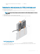
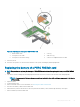


5 Align the following:
a screw holes on the PERC 9 mini blade controller with the standos on the system board connector.
b slots on the PERC 9 mini blade controller edge with the tabs on the support bracket.
6 Lower the PERC 9 mini blade controller onto the connector on the system board.
7 Tighten the two retention screws on the hard-drive/SSD backplane cable connector to secure the card on to the system board.
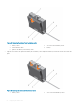
8 Install the tethered battery cable, if applicable.
9 Close the clamp.
10 Install the NDC riser.
11 Close the system.
12 Reconnect the system to its electrical outlet and turn the system on, including any attached peripherals.
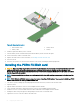
Removing the PERC FD33xD Card
CAUTION: Many repairs may only be done by a certied service technician. You should only perform troubleshooting and simple
repairs as authorized in your product documentation, or as directed by the online or telephone service and support team.
Damage due to servicing that is not authorized by Dell is not covered by your warranty. Read and follow the safety instructions
that are shipped with your product.
NOTE: It is recommended that you always use a static mat and static strap while working on components in the interior of the
system.
NOTE: PERC FD33xS and FD33xD cards are supported only on PowerEdge FD332 system. The procedure for removing a PERC
FD33xS card is identical to removing a PERC FD33xD card.
1 Turn o the system, including any attached peripherals, and disconnect the system from the electrical outlet and peripherals.
2 Open the system.
3 Locate the PERC card.
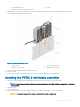
4 Loosen the screws securing the cable to the PERC card.
5 Lift the cable away from the PERC card by holding the cable touch point.
6 Holding the touch point, allow the cable to slowly retract into the cable coil.
7 Remove the screws securing the PERC card to the PERC card holder.
8 Holding it by the touch points, lift the PERC card from the connector on the midplane interface module.
54
Deploying the PERC card