Dell EMC PowerEdge RAID Controller 10 User’s Guide PERC H345, H740P, H745, H745P MX, and H840 Regulatory Model: UCSA-1051, UCSF-1050, UCPA-1001, UCPB-1000, UCPA-1051, UCPA-1050, UCPJ-1000 and UCPE-1000 May 2021 Rev.
Notes, cautions, and warnings NOTE: A NOTE indicates important information that helps you make better use of your product. CAUTION: A CAUTION indicates either potential damage to hardware or loss of data and tells you how to avoid the problem. WARNING: A WARNING indicates a potential for property damage, personal injury, or death. © 2017-2021 Dell Inc. or its subsidiaries. All rights reserved. Dell, EMC, and other trademarks are trademarks of Dell Inc. or its subsidiaries.
Contents Chapter 1: Overview...................................................................................................................... 8 Supported operating systems...........................................................................................................................................8 PERC card specifications..................................................................................................................................................
Using persistent hot spare slots.............................................................................................................................. 29 Physical disk hot swapping....................................................................................................................................... 30 Using replace member and revertible hot spares................................................................................................ 30 Controller cache.......................
Entering the HII configuration utility............................................................................................................................ 56 Exiting the HII configuration utility............................................................................................................................... 56 Navigating to Dell PERC 10 configuration utility.......................................................................................................
Importing secure virtual disk...........................................................................................................................................74 Import secured non-RAID disk....................................................................................................................................... 74 Dell EMC OpenManage Secure Enterprise Key Manager........................................................................................
Target disk fails during replace member operation............................................................................................. 85 A member disk failure is reported in the virtual disk which undergoes replace member operation........ 85 Linux operating system errors........................................................................................................................................86 Virtual disk policy is assumed as write-through error message...............................
1 Overview The PowerEdge RAID Controller (PERC) 10 series consist of the H345, H740P, H745, H745P MX, and H840 cards. The PERC 10 family of storage controller cards has the following characteristics: ● Complies with serial-attached SCSI (SAS) 3.0 providing up to 12 Gb/sec throughput. ● Supports Dell-qualified serial-attached SCSI (SAS) hard drives, SATA hard drives, and solid-state drives (SSDs). ● Offers RAID control capabilities including support for RAID levels 0, 1, 5, 6, 10, 50, and 60.
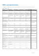
PERC card specifications The table below lists and describes the different PERC cards that consist of the PERC 10 series and their specifications: Table 1.
Table 1.
Dell OpenManage Storage Management Dell OpenManage Storage Management is a storage management application for Dell systems that provides enhanced features for configuring locally attached RAID disk storage. The Dell OpenManage storage management application enables you to perform controller and enclosure functions for all supported RAID controllers and enclosures from a single graphical or command-line interface (CLI).
2 Getting Started The Dell PowerEdge RAID Controller (PERC) 10 series of cards consist of the H345, H740P, H745, H745P MX, and H840 cards. Topics: • • • • • • • PERC PERC PERC PERC PERC PERC PERC H345 front card H345 adapter H740P adapter H745 front card H745 adapter H745P MX card H840 adapter card PERC H345 front card Figure 1. Features of PERC H345 front card 1. PCIe cable connector 3. SAS/SATA backplane connector B 5. Power connector 12 Getting Started 2. Heat sink 4.
PERC H345 adapter Figure 2. Features of PERC H345 adapter 1. Heat sink 3. SAS/SATA backplane connector A 2. SAS/SATA backplane connector B 4. PCIe connector PERC H740P adapter The PERC H740P is the performance RAID solution card consisting of 8 GB non-volatile cache and is available in the adapter (low profile and full height) and mini monolithic form factors for internal storage. Figure 3. Features of PERC H740P adapter 1. Heat sink 3. Battery cable 5. Port B 2. Battery 4. Battery-cable connector 6.
Figure 4. Features of PERC H740P mini monolithic card 1. Heat sink 2. Battery 3. Battery cable PERC H745 front card Figure 5. Features of PERC H745 front card 1. 3. 5. 7. 14 PCIe cable connector Heat sink SAS/SATA backplane connector B Power connector Getting Started 2. Battery 4. Battery cable connector 6.
PERC H745 adapter Figure 6. Features of PERC H745 adapter 1. Heat sink 3. Battery cable connector 5. SAS/SATA backplane connector A 2. Battery 4. SAS/SATA backplane connector B 6. PCIe connector PERC H745P MX card The PERC H745P MX is the RAID solution card for the MX7000 chassis. 8 GB of non-volatile cache manages the drives from its local enclosure and from the MX5016s storage enclosure. Figure 7. Features of PERC H745P MX card 1. Mezzanine connector 3. Heat sink 5. Battery-cable connector 2.
PERC H840 adapter card The PERC H840 is similar to the H740P solution, except that it supports external storage. The PERC H840 is only available in the Adapter (low profile and full height) form factor. Figure 8. Features of PERC H840 adapter card 1. Heat sink 3. Battery cable 5. Port B/1 16 Getting Started 2. Battery 4. Battery-cable connector 6.
3 Features Topics: • • • • • • • Controller features Virtual disk features Hard drive features Fault tolerance Operating system device enumeration Controller mode Non-RAID disk Controller features This section lists the following controller features supported on PowerEdge RAID Controller (PERC) 10 cards in detail: ● 1 MB I/O ● Auto Configure RAID 0 ● Disk roaming ● FastPath ● H745P MX enclosure support ● Non-RAID disk ● Physical disk power management ● PERC H840 enclosure support ● Profile Management ● Se
Using disk roaming Perform the following steps to use disk roaming: 1. Turn off the power to the system, physical disks, enclosures, and system components. 2. Disconnect power cables from the system. 3. Move the physical disks to desired positions on the backplane or the enclosure. 4. Perform a safety check. Make sure the physical disks are inserted properly. 5. Turn on the system. The controller detects the RAID configuration from the configuration data on the physical disks.
Figure 9. Multipath topology for the MX7000 modular system In this illustration, the H745P MX resides in the compute sled and functions as an interface to the SAS topology of the MX7000. The H745P MX is used to configure drives that are located in the MX5016s storage sled into RAID volumes. The H745P MX connects to a pair of MX5000s SAS I/O modules (IOMs) that manage connections between the compute and storage sleds in the MX7000. For more information about configuring drive assignments, see the www.dell.
Physical disk power management Physical disk power management is a power-saving feature of PERC 10 series cards. The feature allows disks to be spun down based on disk configuration and I/O activity. The feature is supported on all rotating SAS and SATA disks, and includes unconfigured and hot-spare disks. The physical disk power management feature is disabled by default.
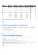
1. To connect a single enclosure, cable the ports so that the enclosure is connected to both the ports on the controller card. 2. To connect multiple enclosures, connect two cables from the controller to the first enclosure as in case in point no 1. Next, connect cables from the first enclosure to the second enclosure. From here, continue to connect two cables from the last enclosure in the chain to the next enclosure you wish to include until you have up to 4 enclosures connected. Figure 11.
Setting up redundant path support on the PERC H840 adapter The PERC H840 card can detect and use redundant paths to disks contained in enclosures. With redundant paths to the same device, if one path fails, another path can be used to communicate between the controller and the device. To connect single enclosure, cable the ports so that the enclosure is connected to both the ports on the controller card. See Figure 6.
● ● ● ● ● ● ● Single virtual disk performance or latency in hypervisor configurations Virtual disk write cache policy Virtual disk read cache policy Virtual disk migration Virtual disk Initialization Reconfiguration of virtual disk Background operations Virtual disk write cache policies The write cache policy of a virtual disk determines how the controller handles writes to the virtual disk. Table 3.
Table 4. Read policies (continued) Feature Description Adaptive read ahead Adaptive read ahead is no longer supported. Selecting adaptive read ahead is equivalent to selecting the read ahead option. Virtual disk migration The PERC 10 series supports migration of virtual disks from one controller to another without taking the target controller offline. The controller can import RAID virtual disks in optimal, degraded, or partially degraded states. You cannot import a virtual disk that is offline.
Fast initialization A fast initialization on a virtual disk overwrites the first and last 8 MB of the virtual disk, clearing any boot records or partition information. The operation takes only 2–3 seconds to complete, but it is followed by BGI, which takes a longer time to complete. To perform a fast initialization using the HII Configuration Utility, see Configuring virtual disk parameters. NOTE: During full or fast initialization, the host cannot access the virtual disk.
See the following table for a list of RLM or OCE options: The source RAID level column indicates the virtual disk RAID level before the RLM or OCE operation and the target RAID level column indicates the RAID level after the RLM or OCE operation. Table 5. RAID level migration Source RAID Level Target RAID Level Number of Physical Number of Disks (Beginning) Physical Disks (End) Capacity Expansio n Possible Description RAID 0 RAID 0 1 or more 2 or more Yes Increases capacity by adding disks.
Background operations Background initialization Background initialization (BGI) is an automated process that writes parity or mirror data on newly created virtual disks. BGI does not run on RAID 0 virtual disks. You can control the BGI rate in the Dell OpenManage storage management application. Any change to the BGI rate does not take effect until the next BGI is executed. NOTE: ● On PERC H345, background operations will not run until the operating system boots. ● You cannot disable BGI permanently.
Instant secure erase Instant secure erase (ISE) drives use the same encryption technology as SED drives but do not allow the encryption key to be secured. The encryption technology allows the drive to be re-purposed and securely erased using the cryptographic erase function. NOTE: ISE drives do not provide protection against theft. 4 KB sector disk drives PERC 10 controllers support 4 KB sector disk drives, which enables you to efficiently use the storage space.
NOTE: To enable automatic replace member, use the Dell OpenManage storage management application. Patrol Read The Patrol read feature is designed as a preventative measure to ensure physical disk health and data integrity. Patrol read scans and resolves potential problems on configured physical disks. The Dell OpenManage storage management application can be used to start patrol read and change its behavior.
Table 6. Drive state/operation (continued) Drive state/operation Unconfigured slot Slot configured in VD Insert configured locked drive into the system (unlockable) Foreign Cryptographic Erase (If configured VD is not secured) ● Rebuild or copyback start ● Original drive data lost Insert locked drive into the system (non-unlockable) Foreign locked Foreign locked Physical disk hot swapping NOTE: To check if the backplane supports hot swapping, see your system owner's manual.
Controller cache preservation The controller is capable of preserving its cache in the event of a system power outage or improper system shutdown. The PERC 10 series controller is attached to a battery backup unit (BBU) that provides backup power during system power loss to preserve the controller's cache data. Cache preservation with non-volatile cache The non-volatile cache (NVC) allows controller cache data to be stored indefinitely.
The order for H740P, H745, H745P MX, H840 is: 1. Non-RAID disks are enumerated first based on slot ID. 2. Virtual disks are enumerated second based on virtual disk target ID. NOTE: If a virtual disk target ID occupies the slot ID, a non-RAID disk may not display in the slot order. NOTE: OS enumeration may not be in this order if virtual disks or non-RAID disks are created while the operating system is running.
Controller operating mode Enhanced HBA mode (H740, H745, H745P MX) RAID mode (H740, H745) RAID mode (H745P MX, H840) RAID mode (H345) Write back-caching Yes (VDs only) Yes Yes No Key management support (see Security key and RAID management) LKM SEKM and LKM LKM No Patrol read Yes (VDs only) Yes Yes Yes (VDs only) reset, and when unconfigured disks are hot-inserted. Non-RAID disk A non-RAID disk is a single disk that is presented and accessible to the host for I/O.
4 Deploying the PERC card This section provides a set of high-level installation and removal instructions for the Dell PowerEdge RAID Controllers (PERC) 10 series. NOTE: For detailed information on cabling the PERC 10 cards, see the system documentation at https://www.dell.com/ poweredgemanuals.
7. Reinstall the riser on the system board and fasten the riser. 8. Close the system. 9. Reconnect the system to its electrical outlet and turn the system on, including any attached peripherals. Figure 12. Removing and installing the PERC H345 adapter 1. Heat sink 2. SAS/SATA backplane connector B 3. SAS/SATA backplane connector A 4. PCIe connector 5. Card connector on the system board Installing the PERC H345 adapter CAUTION: Many repairs may only be done by a certified service technician.
7. Attach the connector labeled SAS A to connector SAS A on the backplane, and attach the connector labeled SAS B to connector SAS B on the backplane. 8. Close the system. 9. Reconnect the system to its electrical outlet and turn the system on, including any attached peripherals. Removing the PERC H345 front card CAUTION: Many repairs may only be done by a certified service technician.
Figure 13. Removing and installing the PERC H345 front card 1. PCIe cable connector 2. Heat sink 3. SAS/SATA backplane connector B 4. SAS/SATA backplane connector A 5. Power connector Installing the PERC H345 front card CAUTION: Many repairs may only be done by a certified service technician. You should only perform troubleshooting and simple repairs as authorized in your product documentation, or as directed by the online or telephone service and support team.
Removing the PERC H740P adapter CAUTION: Many repairs may only be done by a certified service technician. You should only perform troubleshooting and simple repairs as authorized in your product documentation, or as directed by the online or telephone service and support team. Damage due to servicing that is not authorized by Dell is not covered by your warranty. Read and follow the safety instructions that are shipped with your product.
Installing the PERC H740P adapter CAUTION: Many repairs may only be done by a certified service technician. You should only perform troubleshooting and simple repairs as authorized in your product documentation, or as directed by the online or telephone service and support team. Damage due to servicing that is not authorized by Dell is not covered by your warranty. Read and follow the safety instructions that are shipped with your product.
Figure 15. Removing and installing the PERC H740P mini monolithic card 1. Cable 2. PERC H740P mini monolithic card 3. Card connector on the system board 4. Card holder Installing the PERC H740P mini monolithic CAUTION: Many repairs may only be done by a certified service technician. You should only perform troubleshooting and simple repairs as authorized in your product documentation, or as directed by the online or telephone service and support team.
NOTE: Ensure that the screws are torqued to 5.5 lb-in (0.60N-m). 7. Close the system. 8. Reconnect the system to its electrical outlet and turn the system on, including any attached peripherals. Removing the PERC H745 adapter CAUTION: Many repairs may only be done by a certified service technician. You should only perform troubleshooting and simple repairs as authorized in your product documentation, or as directed by the online or telephone service and support team.
Figure 16. Removing and installing the PERC H745 adapter 1. Heat sink 2. Battery 3. Battery cable connector 4. SAS/SATA backplane connector B 5. SAS/SATA backplane connector A 6. PCIe connector 7. Card connector on the system board Installing the PERC H745 adapter CAUTION: Many repairs may only be done by a certified service technician.
Removing the PERC H745 front card CAUTION: Many repairs may only be done by a certified service technician. You should only perform troubleshooting and simple repairs as authorized in your product documentation, or as directed by the online or telephone service and support team. Damage due to servicing that is not authorized by Dell is not covered by your warranty. Read and follow the safety instructions that are shipped with your product.
Figure 17. Removing and installing the PERC H745 card 1. PCIe cable connector 2. Battery 3. Heat sink 4. Battery cable connector 5. SAS/SATA backplane connector B 6. SAS/SATA backplane connector A 7. Power connector Installing the PERC H745 front card CAUTION: Many repairs may only be done by a certified service technician. You should only perform troubleshooting and simple repairs as authorized in your product documentation, or as directed by the online or telephone service and support team.
NOTE: Ensure that you connect the cable according to the connector labels on the cable. The cable does not function properly if reversed. 7. Close the system. 8. Reconnect the system to its electrical outlet and turn on the system and any attached peripherals. Removing the PERC H745P MX adapter card CAUTION: Many repairs may only be done by a certified service technician.
Figure 18. Removing and installing the PERC H745P MX adapter 1. Bracket notch (3) 2. Release lever 3. Card bracket 4. Tabs on the system 5. System chassis 6. Card connector on the system board 7. PERC card connector Installing the PERC H745P MX adapter card CAUTION: Many repairs may only be done by a certified service technician. You should only perform troubleshooting and simple repairs as authorized in your product documentation, or as directed by the online or telephone service and support team.
NOTE: The pin on the release lever secures the card to the chassis of the sled. 7. Route the SAS data cable through the clip on the card and through the channel on the inner side of the chassis. 8. Attach the connector labeled "BP SAS" to connector SAS A on the backplane, and attach the connector labeled "CTRL SAS" to SAS-cable connector on the controller card. 9. Close the sled. 10. Insert the sled into the MX chassis and turn on the system and any attached MX chassis peripherals.
5. PERC card connector 6. Card connector on the system board Installing the PERC H840 card CAUTION: Many repairs may only be done by a certified service technician. You should only perform troubleshooting and simple repairs as authorized in your product documentation, or as directed by the online or telephone service and support team. Damage due to servicing that is not authorized by Dell is not covered by your warranty. Read and follow the safety instructions that are shipped with your product.
CAUTION: The force option is for card replacement only. Use of the force option for reasons other than card replacement is not recommended. Perform the following steps to replace the card that is operating in RAID mode with another in eHBA mode: 1. Power on the system. 2. Enter the HII configuration utility. See Entering the HII configuration utility. 3. Change controller to RAID mode. See Manage controller mode. 4. Reboot the system. 5. Import any foreign virtual disks.
5 Driver installation The Dell PowerEdge RAID controller (PERC) 10 series require software drivers to operate with the supported operating systems. This chapter contains the procedures for installing the drivers for the PERC 10 cards. NOTE: The driver for PERC 10 for VMware ESXi is packaged within the VMware ESXi ISO image downloaded from Dell. For more information, see the VMware documentation at www.dell.com/virtualizationsolutions.
3. Click Continue. 4. From the list of drivers displayed, select the driver you require. 5. Select the self-extracting ZIP file and click Run. 6. Copy the driver to a CD, DVD, or USB drive. 7. Repeat this procedure for all the drivers you require. Windows driver installation Before you install the Windows driver for PERC 10, you must first create a device driver media. ● Read the Microsoft Getting Started document that shipped with your operating system.
Updating PERC 10 driver for existing Windows Server 2012 R2 and newer NOTE: Close all applications on your system before you update the driver. 1. Insert the CD, DVD, or USB drive media containing the driver. 2. Select Start > Settings > Control Panel > System. The System Properties screen is displayed. NOTE: The path to System might vary depending on the operating system family. 3. Click the Hardware tab. 4. Click Device Manager. The Device Manager screen is displayed.
Installing or updating the RPM driver package with KMOD support NOTE: This procedure is applicable for Red Hat Enterprise Linux 7.x. Perform the following steps to install the RPM package with KMOD support: 1. Uncompress the gzipped tarball driver release package. 2. Install the driver package using the command: rpm –ihv kmodmegaraid_ sas-.rpm. NOTE: Use rpm -Uvh when upgrading an existing package. 3.
NOTE: Ensure that you disconnect the driver media so that the drivers are loaded successfully. If the installation media is deleted, reattach it. 10. Press C or exit to go to the installation.
6 Firmware This section provides information about downloading and installing the firmware using Dell Update Package (DUP). Topics: • Installing the firmware using DUP Installing the firmware using DUP 1. Navigate to www.dell.com/support/home. 2. Locate your controller. 3. Download the DUP. a. For Window/iDRAC update, download Windows executable file. b. For Linux update, download .bin file. NOTE: For VMware, firmware should be updated through iDRAC or the PERC CLI utlitily. 4. Install the DUP. a.
7 HII configuration utility The Human Interface Infrastructure (HII) configuration utility is a storage management application integrated into the System BIOS . It is used to configure and manage RAID disk groups, virtual disks, and physical disks. This utility is independent of the operating system.
HII Configuration utility dashboard view options The first screen that is displayed when you access the HII Configuration Utility is the Dashboard View screen. The following table provides detailed information about the options available on the Dashboard View screen. Table 7.
Creating virtual disks 1. Enter the Dell PERC 10 Configuration Utility. See Navigating to Dell PERC 10 configuration utility. 2. Click Main Menu > Configuration Management > Create Virtual Disk. The following list of options are displayed for you to define the virtual disk parameters: ● Select RAID level — allows you to choose the RAID level of your choice. ● Secure Virtual Disk — If you want to create a secured virtual disk, select Secure Virtual Disk.
Table 8. Configuring virtual disk parameters (continued) Virtual disk parameters Description Default Initialization Displays the virtual disk initialization options. You can set the default initialization to: ● No — The virtual disk is not initialized. ● Fast — The first 8 MB of the virtual disk is initialized. ● Full — The entire virtual disk is initialized. For more information, see Virtual disk initialization. By default, the default initialization is set to No. Creating profile based virtual disk 1.
2. Click Main Menu > Controller Management > Advanced Controller Management. 3. Click Clear Controller Events. A screen is displayed indicating that the operation is completed successfully. 4. Click Ok. Saving controller events 1. Enter the Dell PERC 10 Configuration Utility. See Navigating to Dell PERC 10 configuration utility. 2. Click Main Menu > Controller Management > Advanced Controller Management. 3. Click Save Controller Events.
CAUTION: Only use force switch controller mode as part of a controller replacement operation. Consult with technical support for assistance. 4. Check the box to Confirm the controller mode change. 5. Click Yes to confirm the selection. 6. Click OK to acknowledge the change. A reboot is required to complete the mode transition. Until this reboot is performed, avoid requesting any further changes.
5. Click Apply Changes. Enabling physical disk power management 1. Enter the Dell PERC 10 Configuration Utility. See Navigating to Dell PERC 10 configuration utility. 2. Click Main Menu > Controller Management > Advanced Controller Properties. 3. Click Physical Disk Power Management. The following list of options is displayed: ● Time Interval for Spin Down — allows the user to specify the delay time before a disk is spun down.
3. In the Controller Properties section, set the Auto Import Foreign Configuration option to Disabled. 4. Click Apply Changes. The auto import is disabled successfully. Selecting boot mode 1. Enter the Dell PERC 10 Configuration Utility. See Navigating to Dell PERC 10 configuration utility. 2. Click Main Menu > Controller Management > Advanced Controller Properties. 3. In the CONTROLLER PROPERTIES section, select boot mode from the Boot Mode drop-down box.
NOTE: In Select Boot Device, you will not be able to view 4K devices. To view all the virtual disks created, navigate to the Virtual Disk Management screen in HII. For more information, see Virtual disk management. NOTE: If no boot device is selected, the first virtual disk will be set as the boot device on the next reboot. A Non-RAID disk will not be auto-selected as the boot device. 4. Click Apply Changes. Boot support is enabled for the selected controller.
Table 11. Advanced properties of the virtual disk Option Description Logical sector size Indicates the logical sector size of this virtual disk. Strip element size Indicates the strip element size for the virtual disk. Status Indicates the status of the virtual disk. Secured Indicates whether the virtual disk is secured or not. Bad blocks Indicates whether the virtual disk has corrupted blocks. Viewing physical disks associated with a virtual disk 1. Enter the Dell PERC 10 Configuration Utility.
Configuring Virtual Disks When configuring the virtual disks, you should consider the workload intended; RAID1: for simple boot disk; RAID5 or 6: for file or web servers (sequential reads/writes of files); RAID10: for transactional database (small random reads and writes). Virtual disks configured on hard drives should use the controller default cache setting of Write Back and Read Ahead. Virtual disks configured on SSDs can use the same controller defaults settings as hard drives.
Physical disk management Viewing physical disk properties 1. Enter the Dell PERC 10 Configuration Utility. See Navigating to Dell PERC 10 configuration utility. 2. Click Main Menu > Physical Disk Management. All the physical disks associated with the RAID controller are displayed. 3. To view the properties, click on the physical disk. The following properties can be viewed on the physical disk: Table 13.
Table 14. Advanced physical disk properties (continued) Option Description SMART status SMART status of a physical disk. Revision Firmware version of the physical disk. SAS address SAS address of the physical disk. Physical disk power state Power condition (On or Power Save) of the physical disk. Disk cache settings Disk cache settings. NOTE: Disk cache for SATA Gen3 drives is disabled by default. Hard disk drive RPM RPM of the hard drive. Available space Available size of the physical disk.
NOTE: If the drive installed is neither SED or ISE capable, then only the Physical Disk Erase option is displayed. 5. Click Go. A screen is displayed asking if you are sure you want to perform the operation. 6. Select the Confirm option. 7. Click Yes. The physical disk erase operation is completed successfully. Assigning global hot spare To assign a global hot spare from the HII Configuration Utility, perform the following steps: 1. Enter the Dell PERC 10 Configuration Utility.
Convert to Non-RAID disk To assign a disk from the HII Configuration Utility, perform the following steps: 1. Enter the Dell PERC 10 Configuration Utility. See Navigating to Dell PERC 10 configuration utility. 2. Click Main Menu > Physical Disk Management. The list of physical disks appears. 3. Select the physical disk. 4. From the Operations drop-down menu, select Convert to Non-Raid disk. 5. Click Go. A screen appears asking if you are sure you want to perform the operation. 6. Select the Confirm option.
Viewing physical disks associated with an enclosure 1. Enter the Dell PERC 10 Configuration Utility. See Navigating to Dell PERC 10 configuration utility. 2. Click Main Menu > Hardware Components > Enclosure Management. 3. From the Select Enclosure field, choose the enclosure for which you need to view the physical disks. All the physical disks that are associated with the virtual disk are displayed. 4. Click the Attached Physical Disks drop-down box.
8 Security key and RAID management Topics: • • • • • • • • • • • Security key implementation Local Key Management Creating security key Changing Security Settings Disabling security key Create secured virtual disk Secure non-RAID disks Secure preexisting virtual disk Importing secure virtual disk Import secured non-RAID disk Dell EMC OpenManage Secure Enterprise Key Manager Security key implementation The Dell PowerEdge RAID Controller (PERC) 10 series of cards support Self-Encrypting Disks (SED) for prot
NOTE: Passphrase is case-sensitive. You must enter minimum 8 or maximum 32 characters. Ensure that the characters contain at least one number, one lower case letter, one upper case letter, and one non-alphanumeric character. 8. In the Confirm field, re-enter the passphrase to confirm. NOTE: If the Passphrase entered in the Passphrase and Confirm fields do not match, then you are prompted with an error message to enter the passphrase again. 9.
3. Select the Secure Virtual Disk option. 4. Click Create Virtual Disk. The secure virtual disk is created successfully. Secure non-RAID disks In HII, secure non-RAID disks by using the security settings of the controller. 1. Enter the Dell PERC 10 Configuration Utility. See Navigating to Dell PERC 10 configuration utility. 2. Click Main Menu > Physical Disk Management. The list of virtual disks is displayed. 3. Select a non-RAID disk. 4. From the Operations drop-down menu, select Secure Non-RAID Disk.
NOTE: If Auto-Configure for non-RAID disk is enabled, the disk becomes a non-RAID disk. Else, it is unconfigured. Dell EMC OpenManage Secure Enterprise Key Manager This feature allows the PERC to receive a security key from a remote server instead of saving the key on a local controller. This protects data on secured disks under the PERC if the disks or entire system is stolen. Refer to the www.dell.
Migration of drives from local key management to enterprise key management Local key management drives can be migrated to an enterprise key management enabled system, but the controller cannot be transitioned from local key management mode to enterprise key manager mode or the reverse without first disabling security on the controller. Perform the following steps to migrate local key management drives to enterprise key management: 1. Save the current local key management security key. 2.
9 Troubleshooting To get help with your Dell PowerEdge RAID Controller (PERC) 10 series, you can contact your Dell Technical Service representative or see https://www.dell.com/support.
Corrective Action: Contact Dell Technical Support. BIOS disabled error message Error Message: BIOS Disabled. No Logical Drives Handled by BIOS. Probable Cause: This warning message is displayed after you disable the ROM option in the configuration utility. When the ROM option is disabled, the BIOS cannot boot to Int 13h and cannot provide the ability to boot from the virtual disk.
Discovery error message Error Message: A discovery error has occurred, please power cycle the system and all the enclosures attached to this system. Probable Cause: This message indicates that discovery did not complete within 120 seconds. The SAS cables for your system might be improperly connected. Corrective Action: Check the cable connections and fix any problems. Restart the system.
Foreign configuration found error message Error Message: Foreign configuration(s) found on adapter. Press any key to continue, or ’C’ to load the configuration utility or ’F’ to import foreign configuration(s) and continue. Probable Cause: When a controller firmware detects a physical disk with existing foreign metadata, it flags the physical disk as foreign and generates an alert indicating that a foreign disk was detected.
Preserved Cache State The controller preserves the dirty cache from a virtual disk if the virtual disk goes offline or is deleted because of missing physical disks. This preserved dirty cache is called pinned cache and is preserved until you import the virtual disk or discard the cache. 1. Import the virtual disk—Power off the system, re-insert the virtual disk and restore the system power. Use the HII Configuration Utility to import the foreign configuration. 2.
General issues PERC card has yellow bang in device manager Issue: The device is displayed in Device Manager but has a yellow bang (exclamation mark). Corrective Action: Reinstall the driver. For more information on reinstalling drivers, see Driver installation. PERC card not seen in device manager Issue: The device does not appear in the Device Manager. Corrective Action: Turn off the system and reseat the controller. For more information, see Deploying the PERC card.
Multiple disks are inaccessible Issue: Multiple disks are simultaneously inaccessible. Probable Cause: Multiple physical disk errors in a single array typically indicate a failure in cabling or connection and could involve the loss of data. Corrective Action: You can recover the virtual disk after multiple physical disks become simultaneously inaccessible. Perform the following steps to recover the virtual disk: CAUTION: Follow the safety precautions to prevent electrostatic discharge. 1. 2. 3. 4. 5.
Redundant virtual disk fails during reconstruction Issue: Multiple disks fails during a reconstruction process on a redundant virtual disk that has a hot spare. Probable Cause: Multiple physical disks in the virtual disk is failed or the cables are disconnected. Corrective Action: No action is required. The physical disk to which a reconstruction operation is targeted reverts to Ready state, and the virtual disk goes to Failed state.
Smart error detected on a physical disk in a non-redundant virtual disk Issue: A SMART error is detected on a physical disk in a non-redundant virtual disk. Corrective Action: Perform the following steps: 1. Back up your data. 2. Use Replace Member or set up a global hot spare to replace the disk automatically. NOTE: For more information about the Replace Member feature, see the topic Configuring hot spare. 3. Replace the affected physical disk with a new physical disk of equal or higher capacity. 4.
Linux operating system errors Virtual disk policy is assumed as write-through error message Error: kernel: sdb: asking for cache data failed kernel: sdb: assuming drive cache: write through Corrective Action: The error message is displayed when the Linux Small Computer System Interface (SCSI) mid-layer asks for physical disk cache settings.
If the drive is in the Advanced Host Controller Interface (AHCI) mode, the status LED indicator does not power on. Drive status indicator behavior is managed by Storage Spaces Direct. Not all drive status indicators may be used. Table 17.
10 Appendix RAID description RAID is a group of independent physical disks that provides high performance by increasing the number of disks used for saving and accessing data. CAUTION: In the event of a physical disk failure, a RAID 0 virtual disk fails, resulting in data loss. A RAID disk subsystem offers the following benefits: ● Improved I/O performance and data availability. ● Improved data throughput because several disks are accessed simultaneously.
NOTE: The maximum number of virtual disks is currently limited to 192, because of the supported enclosure configuration. RAID 10 configuration In PERC 10 and PERC 11 controllers, RAID 10 can be configured without spanning up to 32 drives. Any RAID 10 volume that has more than 32 drives require spanning. Each span can contain up to 32 drives. Drives must be distributed evenly across all the spans with each span containing an even number of drives.
Table 19. RAID 10 configurations (continued) Disk or span count RAID 10 capable Disk or span count RAID 10 capable Disk or span count RAID 10 capable Disk or span count RAID 10 capable 60 (2) Yes 120 (4) Yes 180 (6) Yes 240 (8) Yes 62 No 122 No 182 (7) Yes - - RAID terminology Disk striping Disk striping allows you to write data across multiple physical disks instead of just one physical disk.
Spanned RAID levels Spanning is a term used to describe the way in which RAID levels 10, 50, and 60 are constructed from multiple sets of basic, or simple RAID levels. For example, a RAID 10 has multiple sets of RAID 1 arrays where each RAID 1 set is considered a span. Data is then striped (RAID 0) across the RAID 1 spans to create a RAID 10 virtual disk. Similarly, RAID 50 and RAID 60 combine multiple sets of RAID 5 or RAID 6 respectively with striping.
11 Getting help Topics: • • • • Recycling or End-of-Life service information Contacting Dell Locating the Express Service Code and Service Tag Receiving automated support with SupportAssist Recycling or End-of-Life service information Take back and recycling services are offered for this product in certain countries. If you want to dispose of system components, visit www.dell.com/recyclingworldwide and select the relevant country.
Figure 25. Locating the Express Service Code and Service tag 1. Information tag (front view) 3. OpenManage Mobile (OMM) label 5. Service Tag, Express Service Code, QRL label 2. Information tag (back view) 4. iDRAC MAC address and iDRAC secure password label The Mini Enterprise Service Tag (MEST) label is located on the rear of the system that includes Service Tag (ST), Express Service Code (Exp Svc Code), and Manufacture Date (Mfg. Date).
12 Documentation resources This section provides information about the documentation resources for your system. To view the document that is listed in the documentation resources table: ● From the Dell EMC support site: 1. Click the documentation link that is provided in the Location column in the table. 2. Click the required product or product version. NOTE: To locate the product name and model, see the front of your system. 3. On the Product Support page, click Manuals & documents.
Table 20. Additional documentation resources for your system (continued) Task Managing your system Document Location For information about installing the operating system, see the operating system documentation. www.dell.com/operatingsystemmanuals For information about updating drivers and firmware, see the Methods to download firmware and drivers section in this document. www.dell.