
Users Guide
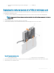
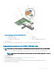


3 tethered battery cable 4 battery
5 guide for the battery on the battery carrier
8 Align the battery carrier with the guide pin slots on the chassis and lower the battery carrier until the guide pin slots on the battery
carrier engage with the guide pins on the chassis
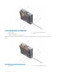
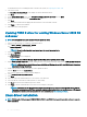
Figure 20. Replacing the battery carrier
1
battery carrier 2 tab on the battery carrier
3 guide slot on the chassis 4 guide pins on the chassis
9 Connect the battery cable to PERC 9 mini blade controller.
10 Close the system.
11 Reconnect the system to its electrical outlet and turn on the system, including any attached peripherals.
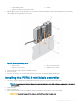
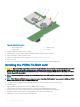
Installing the PERC 9 mini blade controller
1 Turn o the system, including any attached peripherals, and disconnect the system from the electrical outlet.
NOTE
: It is recommended that you always use a static mat and static strap while working on components in the interior
of the system.
2 Open the system.
3 Remove the NDC riser.
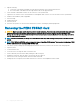
4 Lift the clamp attached to the power supply bay and locate the PERC 9 card connector on the system board.
CAUTION
: To prevent damage to the card, you must hold the card by its edges only.
Deploying the PERC card 53