
Users Guide
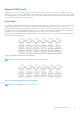
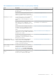
Table Of Contents
- Dell EMC PowerEdge RAID Controller 10 User’s Guide PERC H345, H740P, H745, H745P MX, and H840
- Contents
- Overview
- Getting Started
- Features
- Controller features
- Virtual disk features
- Hard drive features
- Fault tolerance
- Operating system device enumeration
- Controller mode
- Non-RAID disk
- Deploying the PERC card
- Removing the PERC H345 adapter
- Installing the PERC H345 adapter
- Removing the PERC H345 front card
- Installing the PERC H345 front card
- Removing the PERC H740P adapter
- Installing the PERC H740P adapter
- Removing the PERC H740P mini monolithic
- Installing the PERC H740P mini monolithic
- Removing the PERC H745 adapter
- Installing the PERC H745 adapter
- Removing the PERC H745 front card
- Installing the PERC H745 front card
- Removing the PERC H745P MX adapter card
- Installing the PERC H745P MX adapter card
- Removing the PERC H840 card
- Installing the PERC H840 card
- Part replacement of a PERC card in eHBA mode
- Part replacement of a PERC card in RAID mode with another in eHBA mode
- Driver installation
- Creating the device driver media
- Windows driver installation
- Installing the driver during a Windows Server 2012 R2 and newer installation
- Installing the driver after Windows Server 2012 R2 and newer installation
- Updating PERC 10 driver for existing Windows Server 2012 R2 and newer
- Linux driver installation
- Firmware
- HII configuration utility
- Entering the HII configuration utility
- Exiting the HII configuration utility
- Navigating to Dell PERC 10 configuration utility
- HII Configuration utility dashboard view options
- Configuration management
- Controller management
- Virtual disk management
- Physical disk management
- Hardware components
- Security key management in the HII configuration utility
- Security key and RAID management
- Security key implementation
- Local Key Management
- Creating security key
- Changing Security Settings
- Disabling security key
- Create secured virtual disk
- Secure non-RAID disks
- Secure preexisting virtual disk
- Importing secure virtual disk
- Import secured non-RAID disk
- Dell EMC OpenManage Secure Enterprise Key Manager
- Troubleshooting
- Single virtual disk performance or latency in hypervisor configurations
- Adapter at baseport not responding error message
- BIOS disabled error message
- Configured disks removed or not accessible error message
- Dirty cache data error message
- Discovery error message
- Drive Configuration Changes Error Message
- Windows operating system installation errors
- Firmware fault state error message
- Extra enclosure error message
- Foreign configuration found error message
- Foreign configuration not found in HII error message
- Degraded state of virtual disks
- Memory errors
- Preserved Cache State
- Security key errors
- General issues
- Physical disk issues
- Physical disk in failed state
- Unable to rebuild a fault tolerant virtual disk
- Fatal error or data corruption reported
- Physical disk displayed as blocked
- Multiple disks are inaccessible
- Rebuilding data for a failed physical disk
- Virtual disk fails during rebuild using a global hot spare
- Dedicated hot spare disk fails during rebuild
- Redundant virtual disk fails during reconstruction
- Virtual disk fails rebuild using a dedicated hot spare
- Physical disk takes a long time to rebuild
- SMART errors
- Replace member errors
- Linux operating system errors
- Drive indicator codes
- HII error messages
- Appendix RAID description
- Getting help
- Documentation resources

Spanned RAID levels
Spanning is a term used to describe the way in which RAID levels 10, 50, and 60 are constructed from multiple sets of basic, or
simple RAID levels. For example, a RAID 10 has multiple sets of RAID 1 arrays where each RAID 1 set is considered a span. Data is
then striped (RAID 0) across the RAID 1 spans to create a RAID 10 virtual disk. Similarly, RAID 50 and RAID 60 combine multiple
sets of RAID 5 or RAID 6 respectively with striping.
Parity data
Parity data is redundant data that is generated to provide fault tolerance within certain RAID levels. In the event of a disk failure,
the parity data can be used by the controller to regenerate user data. Parity data is present for RAID 5, 6, 50, and 60.
The parity data is distributed across all the physical disks in the system. If a single physical disk fails, it can be rebuilt from the
parity and the data on the remaining physical disks. RAID level 5 combines distributed parity with disk striping. Parity provides
redundancy for one physical disk failure without duplicating the contents of the entire physical disks.
RAID 6 combines dual distributed parity with disk striping. This level of parity allows for two disk failures without duplicating the
contents of entire physical disks.
Figure 23. Example of Distributed Parity (RAID 5)
NOTE: Parity is distributed across multiple physical disks in the disk group.
Figure 24. Example of Dual Distributed Parity (RAID 6)
NOTE: Parity is distributed across all disks in the array.
Appendix RAID description 91