Dell™ PowerEdge™ SC1425 Systems Installation and Troubleshooting Guide Introduction Indicators, Messages, and Codes Finding Software Solutions Running the System Diagnostics Troubleshooting Your System Installing System Components Installing Drives Getting Help Jumpers, Switches, and Connectors I/O Connectors Service-Only Parts Replacement Procedures Notes, Notices, and Cautions NOTE: A NOTE indicates important information that helps you make better use of your computer.
Back to Contents Page Jumpers, Switches, and Connectors Dell™ PowerEdge™ SC1425 Systems Installation and Troubleshooting Guide Jumpers—A General Explanation System Board Jumpers System Board Connectors Riser Board Connectors Disabling a Forgotten Password This section provides specific information about the system jumpers. It also provides some basic information on jumpers and switches and describes the connectors on the various boards in the system.
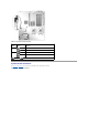
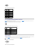
Table A-1. System Board Jumper Settings Jumper Setting Description PASSWD The password feature is enabled. (default) The password feature is disabled. NVRAM_CLR (default) The configuration settings in NVRAM are retained at system boot. The configuration settings in NVRAM are cleared at next system boot. jumpered unjumpered System Board Connectors See Figure A-3 and Table A-2 for the location and description of the system board connectors. Figure A-3.
Table A-2. System Board Connectors Connector Description BATTERY Connector for the 3.
1. Turn off the system and attached peripherals, and disconnect the system from the electrical outlet. 2. Open the system. See "Opening the System" in "Troubleshooting Your System." 3. Remove the password jumper plug. See Figure A-2 to locate the password jumper on the system board. If necessary, remove the riser card insulator to improve access to the jumper. See "Removing the Riser Card" in "Installing System Components." 4. If you removed the riser card insulator in step 3, reinstall it now.
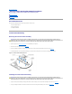
Back to Contents Page I/O Connectors Dell™ PowerEdge™ SC1425 Systems Installation and Troubleshooting Guide Serial Connector PS/2-Compatible Keyboard and Mouse Connectors Video Connector USB Connectors Integrated NIC Connectors Network Cable Requirements I/O connectors are the gateways that the system uses to communicate with external devices, such as a keyboard, mouse, printer, or monitor. This section describes the various connectors on your system.
Table B-2. Serial Connector Pin Assignments Pin Signal I/O Definition 1 DCD I Data carrier detect 2 SIN I Serial input 3 SOUT O Serial output 4 DTR O Data terminal ready 5 GND N/A Signal ground 6 DSR I Data set ready 7 RTS O Request to send 8 CTS I Clear to send 9 RI I Ring indicator N/A Chassis ground Shell N/A PS/2-Compatible Keyboard and Mouse Connectors The PS/2-compatible keyboard and mouse cables attach to 6-pin, miniature DIN connectors.
Pin Signal I/O Definition 1 RED O Red video 2 GREEN O Green video 3 BLUE O Blue video 4 NC N/A No connection 5–8, 10 GND N/A Signal ground 9 VCC N/A Vcc 11 NC N/A No connection 12 DDC data out O Monitor detect data 13 HSYNC O Horizontal synchronization 14 VSYNC O Vertical synchronization 15 NC N/A No connection USB Connectors The system's USB connectors support USB-compliant peripherals such as keyboards, mice, and printers and may also support USB-compliant devi
1 TD+ O Data out (+) 2 TD– O Data out (–) 3 RD+ I Data in (+) 4 NC N/A No connection 5 NC N/A No connection 6 RD– I Data in (–) 7 NC N/A No connection 8 NC N/A No connection Network Cable Requirements The NIC supports a UTP Ethernet cable equipped with a standard RJ45-compatible plug. Observe the following cabling restrictions. NOTICE: To avoid line interference, voice and data lines must be in separate sheaths. l Use Category 5 or greater wiring and connectors.
Back to Contents Page Service-Only Parts Replacement Procedures Dell™ PowerEdge™ SC1425 Systems Installation and Troubleshooting Guide Recommended Tools Control Panel Assembly System Board Recommended Tools You may need the following items to perform the procedures in this section: l Key to the system keylock l Wrist grounding strap l #2 Phillips screwdriver Control Panel Assembly Removing the Control Panel Assembly CAUTION: Many repairs may only be done by a certified service technician.
3. Connect the control panel cables. See Figure C-1. 4. Close the system. See "Closing the System" in "Troubleshooting Your System." System Board The system board provides interface signal routing between the system board and the two SATA hard-drive bays, the optional CD drive, and the control panel. In addition, the power supply is connected to the system board using two cables. The system board and system board tray are removed and replaced as a single assembly.
Installing the System Board Assembly CAUTION: Many repairs may only be done by a certified service technician. You should only perform troubleshooting and simple repairs as authorized in your product documentation, or as directed by the online or telephone service and support team. Damage due to servicing that is not authorized by Dell is not covered by your warranty. Read and follow the safety instructions that came with the product. 1. Unpack the new system board assembly. 2.
NOTE: When installing the cooling shroud, ensure that the two tabs on the cooling shroud are inserted into the two retaining slots in the midchassis wall. 16. Close the system. See "Closing the System" in "Troubleshooting Your System.
Back to Contents Page Introduction Dell™ PowerEdge™ SC1425 Systems Installation and Troubleshooting Guide Other Documents You May Need Your system includes the following significant service and upgrade feature: l System diagnostics, which checks for hardware problems (if the system can boot) The following system options are offered: l Second microprocessor l Additional system memory l Expansion-card options l IDE optical drive Other Documents You May Need The Product Information Guide provides im
Back to Contents Page Indicators, Messages, and Codes Dell™ PowerEdge™ SC1425 Systems Installation and Troubleshooting Guide Front-Panel Indicators and Features Warning Messages Back-Panel Features and Indicators Diagnostics Messages NIC Indicators Alert Messages System Messages Baseboard Management Controller Messages System Beep Codes The system, applications, and operating systems can identify problems and alert you to them.
Hard-drive indicator The green hard-drive activity indicator flashes when the SATA hard drives are in use. NOTE: It does not flash when SCSI hard drives are in use. NMI button The NMI button is used to troubleshoot software and device driver errors when using certain operating systems. This button can be pressed using the end of a paper clip. Use this button only if directed to do so by qualified support personnel or by the operating system's documentation.
Possible system board resource and/or system board hardware failure. See "IRQ Assignment Conflicts" in "Finding Software Solution." If the problem persists, see "Getting Help." Possible expansion card failure. See "Troubleshooting Expansion Cards" in "Troubleshooting Your System." Other failure. Ensure that the diskette drive, optical drive, and hard drives are properly connected. See "Troubleshooting Your System" for the appropriate drive installed in your system.
Yellow 1000-Mbps connection Orange 100-Mbps connection Green 10-Mbps connection System Messages System messages appear on the screen during system boot to notify you of a possible problem with the system. Table 2-4 lists the system messages that can occur and the probable cause and corrective action for each message.
Remove the memory modules in bank 3. See "System Memory" in "Installing System Components." Memory slots DIMM3_A and DIMM3_B must be empty if Dual Rank memory DIMMs are in slots DIMM2_A and DIMM2_B. Gate A20 failure Faulty keyboard controller (faulty system board). See "Getting Help." General failure The operating system is unable to carry out the command. This message is usually followed by specific information. Take the appropriate action to resolve the problem.
PCI Express training error Faulty PCI Express controller. See "Getting Help." Plug & Play Configuration error Plug & Play Configuration error is detected during PCI device scan. Install the NVRAM_CLR jumper and reboot the system. See Figure A-2 for jumper location. If the problem persists, see "Troubleshooting Expansion Cards" in "Troubleshooting Your System.
Code Cause Corrective Action 1-1-2 CPU register test failure See "Troubleshooting the Processors" in "Troubleshooting Your System." 1-1-3 CMOS write/read failure; faulty system board Faulty system board. See "Getting Help." 1-1-4 BIOS error Reflash the BIOS. 1-2-1 Programmable interval-timer failure; faulty system board Faulty system board. See "Getting Help." 1-2-2 DMA initialization failure See "Troubleshooting System Memory" in "Troubleshooting Your System.
Alert Messages Systems management software generates alert messages for your system. Alert messages include information, status, warning, and failure messages for drive, temperature, fan, and power conditions. Baseboard Management Controller Messages The Baseboard Management Controller (BMC) enables you to configure, monitor, and recover systems remotely. BMC uses the system's serial port and integrated NIC1 to support fault logging and SNMP alerting.
Back to Contents Page Finding Software Solutions Dell™ PowerEdge™ SC1425 Systems Installation and Troubleshooting Guide Before You Begin Troubleshooting Errors and Conflicts Software problems can be caused by: l Improper installation or configuration of an application l Application conflicts l Input errors l Interrupt assignment conflicts Ensure that you are installing the software application according to the software manufacturer's recommended procedures.
IRQ2 Interrupt controller 1 to enable IRQ8 through IRQ15 IRQ3 Available IRQ4 Serial port 1 (COM1 and COM3) IRQ5 Available IRQ6 Available IRQ7 Reserved IRQ8 Real-time clock IRQ9 ACPI functions (used for power management) IRQ10 Available IRQ11 Available IRQ12 PS/2 mouse port unless the mouse is disabled through the System Setup program IRQ13 Math coprocessor IRQ14 IDE OPTICAL drive controller (available if IDE CDROM controller is disabled in BIOS setup) IRQ15 Reserved (available if
Back to Contents Page Running the System Diagnostics Dell™ PowerEdge™ SC1425 Systems Installation and Troubleshooting Guide Using Dell Diagnostics System Diagnostics Features When to Use the System Diagnostics Running the System Diagnostics System Diagnostics Testing Options Using the Custom Test Options If you experience a problem with your system, run the diagnostics before calling for technical assistance.
1. Create a set of diagnostics diskettes from the Dell OpenManage Server Assistant CD. See "Using the Dell OpenManage Server Assistant" in your User's Guide for information on creating the diskettes. 2. Obtain a USB diskette drive and connect it to the system. 3. Insert the first diagnostics diskette. 4. Reboot the system. If the system fails to boot, see "Getting Help." When you start the system diagnostics, a message is displayed stating that the diagnostics are initializing.
Back to Contents Page
Back to Contents Page Troubleshooting Your System Dell™ PowerEdge™ SC1425 Systems Installation and Troubleshooting Guide Safety First—For You and Your System Troubleshooting a Damaged System Start-Up Routine Troubleshooting the System Battery Checking Basic Power Problems Troubleshooting the Power Supply Checking the Equipment Troubleshooting System Cooling Problems Troubleshooting Basic I/O Functions Troubleshooting System Memory Troubleshooting a NIC Troubleshooting an Optical Drive Inside th
This section provides troubleshooting procedures for external devices attached to the system, such as the monitor, keyboard, or mouse. Before you perform any of the procedures, see "Troubleshooting External Connections." Troubleshooting External Connections Loose or improperly connected cables are the most likely source of problems for the system, monitor, and other peripherals (such as a printer, keyboard, mouse, or other external device).
2. Examine the mouse and its cable for signs of damage. If the mouse is not damaged, go to step 4. If the mouse is damaged, continue to the next step. 3. Swap the faulty mouse with a working mouse. If the problem is resolved, replace the faulty mouse. See "Getting Help." 4. Enter the System Setup program and ensure that the mouse controller is enabled. See "Using the System Setup Program" in your User's Guide. If the problem is not resolved, see "Getting Help.
Problem l System message indicates a problem with a USB device. l Device connected to a USB port is not operating properly. Action 1. Enter the System Setup program, and ensure that the USB ports are enabled. See "Using the System Setup Program" in your User's Guide. 2. Turn off the system and any USB devices. 3. Disconnect the USB devices, and connect the malfunctioning device to the other USB connector. 4. Turn on the system and the reconnected device.
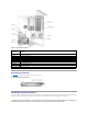
Figure 5-1. Inside the System The system board holds the system's control circuitry and other electronic components. The processor and memory are installed directly on the system board. Using a riser card, the system can accommodate one expansion card. The peripheral bays provide space for up to two hard drives and an optional optical drive. Power is supplied to the system board and drives through one nonredundant power supply. Opening the System The system is enclosed by an optional bezel and cover.
Figure 5-3. Installing and Removing the System Cover Closing the System 1. Ensure that you did not leave tools or parts inside the system. 2. Place the cover over the sides of the chassis, and slide the cover forward. 3. Tighten the two thumbscrews at the back of the system to secure the cover. See Figure 5-3. 4. Replace the system in the rack, and reconnect the peripheral cables. 5.
6. Let the system dry thoroughly for at least 24 hours. 7. Reinstall all of the components that you removed earlier in this procedure. See "Installing an Expansion Card," "Installing Memory Modules," and "Replacing the Processor" in "Installing System Components." 8. Close the system. See "Closing the System." 9. Reconnect the system to the electrical outlet, and turn on the system and attached peripherals. If the system does not start properly, see "Getting Help." 10.
1. Re-enter the time and date through the System Setup program. See "Using the System Setup Program" in your User's Guide. 2. Turn off the system and disconnect it from the electrical outlet for at least one hour. 3. Reconnect the system to the electrical outlet and turn on the system. 4. Enter the System Setup program. If the date and time are not correct in the System Setup program, replace the battery. See "System Battery" in "Installing System Components.
Action CAUTION: Many repairs may only be done by a certified service technician. You should only perform troubleshooting and simple repairs as authorized in your product documentation, or as directed by the online or telephone service and support team. Damage due to servicing that is not authorized by Dell is not covered by your warranty. Read and follow the safety instructions that came with the product. 1. Run the appropriate diagnostic test. See "Using Dell Diagnostics" in Running System Diagnostics.
10. Enter the System Setup program and check the system memory setting. See "Using the System Setup Program" in your User's Guide. If the amount of memory installed does not match the system memory setting, then perform the following steps: a. Turn off the system and attached peripherals, and disconnect the system from its electrical outlet. b. Open the system. See "Opening the System.
l Damaged or improperly connected hard-drive cables. Action CAUTION: Many repairs may only be done by a certified service technician. You should only perform troubleshooting and simple repairs as authorized in your product documentation, or as directed by the online or telephone service and support team. Damage due to servicing that is not authorized by Dell is not covered by your warranty. Read and follow the safety instructions that came with the product.
3. Ensure that the primary SCSI channel is enabled, and restart the system. See the documentation supplied with the controller for information about the configuration utility. 4. Verify that the device drivers are installed and configured correctly. See the operating system documentation. 5. Check the SCSI cable connections inside the system: a. Turn off the system, including any attached peripherals, and disconnect the system from the electrical outlet. b. Open the system. See "Opening the System.
Troubleshooting the Processors Problem l Error message indicates a processor problem. l A heat sink is not installed for each processor. Action CAUTION: Many repairs may only be done by a certified service technician. You should only perform troubleshooting and simple repairs as authorized in your product documentation, or as directed by the online or telephone service and support team. Damage due to servicing that is not authorized by Dell is not covered by your warranty.
22. 23. Close the system. See "Closing the System." Reconnect the system to the electrical outlet, and turn on the system and attached peripherals. If the problem persists, see "Getting Help.
Back to Contents Page Installing System Components Dell™ PowerEdge™ SC1425 Systems Installation and Troubleshooting Guide System Board Components Expansion Cards System Battery Riser Card Fans System Memory Power Supply Processor This section describes how to install the following system components: l System battery l Cooling fans l Power supply l Expansion cards l Riser card l System memory l Processors System Board Components When installing and replacing system board components, us
1. Enter the System Setup program and record the option settings on the System Setup screens. See "Using the System Setup Program" in the User's Guide. 2. Open the system. See "Opening the System" in Troubleshooting Your System." 3. Remove the system battery. See Figure 6-1 to locate the system battery on the system board. a. Pull the latch away from the battery. See Figure 6-2. b. Lift the battery out of the battery socket.
5. Slide the fan modules toward the front of the system to remove them. Figure 6-3. Installing and Removing a Processor/Memory Fan Module Installing a Processor/Memory Fan Module 1. With the fan power cable facing towards the front of the system, align the fan module alignment holes with the alignment pins on the chassis. See Figure 6-3. 2. Align the four alignment pins on the fan brackets with the alignment holes in the fan modules. 3.
Installing the Expansion Card Fan Module 1. With the fan power cable facing towards the rear of the system, align the fan module alignment hole with the alignment pin on the chassis. See Figure 6-4. 2. Install the expansion card fan module against the two tabs and atop the alignment pin on the system chassis. 3. Reconnect the fan module's power cable to the fan interface power cable connected to the system board. See Figure 6-4. 4. Close the system.
Installing the Power Supply 1. Lower the power supply in the system and slide the new power supply backward until the power supply is fully seated. See Figure 6-5). 2. Install the screw that secures the power supply to the chassis. 3. Fit the power supply cable connector into the mid-chassis connector slot. 4. Connect the power supply cable to the interface cable that supplies power to the hard drives and optical drives.
3. Remove the filler bracket. NOTE: Keep this bracket in case you need to remove the expansion card. The filler bracket must be installed over the empty expansion card slot to maintain Federal Communications Commission (FCC) certification of the system. The bracket also keeps dust and dirt out of the system and aid in proper cooling and airflow inside the system. 4.
CAUTION: Many repairs may only be done by a certified service technician. You should only perform troubleshooting and simple repairs as authorized in your product documentation, or as directed by the online or telephone service and support team. Damage due to servicing that is not authorized by Dell is not covered by your warranty. Read and follow the safety instructions that came with the product. 1. Open the system. See "Opening the System" in "Troubleshooting Your System." 2.
l If only one memory module is installed, it must be installed in socket DIMM1_A. l If two or more memory modules are installed, they must be installed in pairs of matched memory size, speed, and technology. l The system supports both single-ranked and dual-ranked memory modules. l If you install both single-ranked and dual-ranked memory modules, the dual-ranked memory modules must be installed in bank 1. l Dual-ranked memory modules are not supported in bank 3.
Installing Memory Modules CAUTION: Many repairs may only be done by a certified service technician. You should only perform troubleshooting and simple repairs as authorized in your product documentation, or as directed by the online or telephone service and support team. Damage due to servicing that is not authorized by Dell is not covered by your warranty. Read and follow the safety instructions that came with the product. 1. Open the system. See "Opening the System" in Troubleshooting Your System." 2.
Processor It is possible to upgrade your processor(s) to take advantage of future options in speed and functionality. Each processor and its associated internal cache memory are contained in a pin grid array (PGA) package that is installed in a zero insertion force (ZIF) socket on the system board. Replacing the Processor CAUTION: Many repairs may only be done by a certified service technician.
the processor. Do not pry the heat sink off of the processor. 6. Lift the heat sink off of the processor and set the heat sink upside down so as not to contaminate the thermal grease. 7. Pull the socket-release lever straight up until the processor is released from the socket. See Figure 6-12. Figure 6-12. Installing and Removing the Processor 8. Lift the processor out of the socket and leave the release lever up so that the socket is ready for the new processor.
15. Press to enter the System Setup program, and check that the processor information matches the new system configuration. See your User's Guide for instructions about using the System Setup program. 16. Run the system diagnostics to verify that the new processor operates correctly. See "Using Dell Diagnostics" for information about running the diagnostics and troubleshooting processor problems.
Back to Contents Page Installing Drives Dell™ PowerEdge™ SC1425 Systems Installation and Troubleshooting Guide Optical Drive SCSI Configuration Information Configuring the Boot Drive Hard Drives Installing a SCSI Controller Card Your system contains up to two SATA or SCSI hard drives and a optical drive. If your system contains SCSI hard drives, they must be connected to a SCSI controller card. The integrated SATA controller supports up to two SATA hard drives.
2. Rotate the drive downward until it snaps into place. 3. Connect the interposer card to the optical drive. 4. Push the plungers into the captive fastener barrels until they snap into place. 5. Connect the interface and power cables to the optical drive's interposer card 6. Close the system. See "Closing the System" in "Troubleshooting Your System.
Remove the CD drive if you are removing hard drive 0. See "Removing the Optical Drive." 3. Disconnect the power and interface cables from the hard drive. The interface cables for SATA hard drives are connected to the system board. See Figure A-3 for the location of the system board connectors. The interface cables for SCSI hard drives are connected to a controller card. 4. Loosen the captive screw that secures the hard-drive carrier to the chassis. See Figure 7-2. Figure 7-2.
Installing a Hard Drive CAUTION: Many repairs may only be done by a certified service technician. You should only perform troubleshooting and simple repairs as authorized in your product documentation, or as directed by the online or telephone service and support team. Damage due to servicing that is not authorized by Dell is not covered by your warranty. Read and follow the safety instructions that came with the product. 1. Align the hard-drive mounting holes with the holes in the drive carrier. 2.
Back to Contents Page Getting Help Dell™ PowerEdge™ SC1425 Systems Installation and Troubleshooting Guide Technical Assistance Dell Enterprise Training and Certification Problems With Your Order Product Information Returning Items for Warranty Repair or Credit Before You Call Contacting Dell Technical Assistance If you need assistance with a technical problem, perform the following steps: 1. Complete the procedures in "Troubleshooting Your System." 2.
support.jp.dell.com (Japan only) support.euro.dell.com (Europe only) l Electronic Quote Service sales@dell.com apmarketing@dell.com (Asian/Pacific countries only) sales_canada@dell.com (Canada only) l Electronic Information Service info@dell.com AutoTech Service Dell's automated technical support service—AutoTech—provides recorded answers to the questions most frequently asked by Dell customers about their portable and desktop computer systems.
the system diagnostics. 4. Include any accessories that belong with the item(s) being returned (such as power cables, media such as CDs and diskettes, and guides) if the return is for credit. 5. Pack the equipment to be returned in the original (or equivalent) packing materials. You are responsible for paying shipping expenses. You are also responsible for insuring any product returned, and you assume the risk of loss during shipment to Dell. Collect-on-delivery (C.O.D.) packages are not accepted.
Department Name or Service Area, Website and E-Mail Address Country (City) International Access Code Country Code City Code Area Codes, Local Numbers, and Toll-Free Numbers Anguilla General Support toll-free: 800-335-0031 Antigua and Barbuda General Support 1-800-805-5924 Argentina (Buenos Aires) Website: www.dell.com.
Sales (med./large bus., government) Cayman Islands toll-free: 1-800-387-5755 Spare Parts Sales & Extended Service Sales 1 866 440 3355 General Support 1-800-805-7541 Chile (Santiago) Country Code: 56 Sales, Customer Support, and Technical Support toll-free: 1230-020-4823 City Code: 2 Tech Support website: support.dell.com.cn Tech Support E-mail: cn_support@dell.
Fax 09 253 313 99 Switchboard 09 253 313 00 Website: support.euro.dell.com E-mail: support.euro.dell.
City Code: 1 Corporate Customer Care (dial within U.K. only) Ireland Sales U.K. Sales (dial within U.K. only) 0870 907 4499 01 204 4444 0870 907 4000 Fax/SalesFax 01 204 0103 Switchboard 01 204 4444 Website: support.euro.dell.com E-mail: support.euro.dell.
Customer Service (Penang, Malaysia) Country Code: 853 Malaysia (Penang) International Access Code: 00 Country Code: 60 City Code: 4 Transaction Sales 604 633 4949 toll-free: 0800 581 Technical Support (Dell Precision, OptiPlex, and Latitude) toll-free: 1 800 88 0193 Technical Support (Dimension and Inspiron) toll-free: 1 800 88 1306 Customer Service 04 633 4949 Transaction Sales toll-free: 1 800 888 202 Corporate Sales toll-free: 1 800 888 213 001-877-384-8979 Customer Technical Support or 001-
Panama General Support 001-800-507-0962 Peru General Support 0800-50-669 Website: support.euro.dell.com Poland (Warsaw) E-mail: pl_support_tech@dell.com Customer Service Phone International Access Code: 011 Customer Care Country Code: 48 City Code: 22 Portugal International Access Code: 00 Sales 57 95 999 Customer Service Fax 57 95 806 Reception Desk Fax 57 95 998 Switchboard 57 95 999 Website: support.euro.dell.com E-mail: support.euro.dell.
Website: support.euro.dell.com E-mail: Tech_support_central_Europe@dell.com Switzerland (Geneva) E-mail for French-speaking HSB and Corporate Customers: support.euro.dell.
Spare Parts Sales toll-free: 1-800-357-3355 Extended Service and Warranty Sales toll-free: 1-800-247-4618 Fax toll-free: 1-800-727-8320 toll-free: 1-877-DELLTTY Dell Services for the Deaf, Hard-of-Hearing, or Speech-Impaired (1-877-335-5889) U.S.
Back to Contents Page Dell™ PowerEdge™ SC1425 Systems Installation and Troubleshooting Guide Notes, Notices, and Cautions NOTE: A NOTE indicates important information that helps you make better use of your computer. NOTICE: A NOTICE indicates either potential damage to hardware or loss of data and tells you how to avoid the problem. CAUTION: A CAUTION indicates a potential for property damage, personal injury, or death.