Dell EMC PowerStore Руководство по работе с сетью для моделей PowerStore X Версия 2.x Июнь 2021 Ред.
Примечания, предупреждения и предостережения ПРИМЕЧАНИЕ: Пометка ПРИМЕЧАНИЕ указывает на важную информацию, которая поможет использовать данное изделие более эффективно. ОСТОРОЖНО: Указывает на возможность повреждения устройства или потери данных и подсказывает, как избежать этой проблемы. ПРЕДУПРЕЖДЕНИЕ: Указывает на риск повреждения оборудования, получения травм или на угрозу для жизни. © Корпорация Dell или ее дочерние компании, 2020-2021. Все права защищены.
Содержание Дополнительные ресурсы............................................................................................................5 Глава 1: Обзор.............................................................................................................................. 6 Общие сведения об устройстве Модель PowerStore X..........................................................................................6 Поддерживаемые коммутаторы............................................................
Глава 8: Начальная настройка устройства Модель PowerStore X................................................42 Мастер начальной настройки...................................................................................................................................... 42 Получение заполненной таблицы начальной настройки................................................................................... 43 Приложение A: Расширение сети хранения для работы на нескольких портах...........................
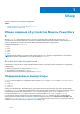
Предисловие Для улучшения продуктов периодически выпускаются обновленные версии программного обеспечения и оборудования. Некоторые функции, описанные в этом документе, поддерживаются не всеми версиями программного обеспечения или оборудования, которые используются на данный момент. Примечания к выпуску продукта содержат последние обновленные сведения о функциях продукта. Если продукт работает ненадлежащим образом либо не так, как описано в этом документе, обратитесь к своему поставщику услуг.
1 Обзор В данную главу включена следующая информация. Темы: • • Общие сведения об устройстве Модель PowerStore X Поддерживаемые коммутаторы Общие сведения об устройстве Модель PowerStore X Модель PowerStore X поддерживает блочные (только сеть хранения данных) рабочие нагрузки и нагрузки vVol с установленным в системе гипервизором. Системное программное обеспечение разворачивается на гипервизоре, что позволяет развертывать виртуальные машины (ВМ) и приложения заказчика на оборудовании.
Дополнительные сведения о коммутаторах Dell EMC серии PowerSwitch под управлением операционной системы 10 Enterprise Edition (OS10EE) см. в следующих документах. Таблица 1. Ресурсы документации по PowerSwitch Документ Справочные материалы Местоположение Руководство по установке Dell EMC PowerSwitch серии S4100-ON Требования к подготовке к работе на сайте PowerSwitch, пошаговые процедуры для монтажа в стойке и монтажа на столе, вставка модулей и подключение к источнику питания.
2 Подготовка к настройке коммутаторов и сетей В этой главе содержится следующая информация. Темы: • • Модель PowerStore X Таблица подготовки к настройке сети Таблица начальной настройки Модель PowerStore X Таблица подготовки к настройке сети Обратитесь к администратору сети, чтобы заполнить таблицу подготовки к настройке сети и зарезервировать необходимую информацию для настройки коммутаторов.
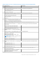
Таблица 2. Модель PowerStore X Таблица подготовки к настройке сети (пустая) (продолжение) Шаг Описание шага Примечания Управление (помеченный) 6. Запишите идентификаторы виртуальной ЛС, которые будут использоваться для производства. Сеть хранения (помеченный) vMotion (помеченный) Внутренняя (непомеченный) 7. Зарезервируйте и запишите IP-адреса, необходимые для настройки следующих коммутаторов. IP-адрес управления для коммутатора 1 IP-адрес управления для коммутатора 2 Шлюз по умолчанию Сервер NTP 8.
Таблица 2. Модель PowerStore X Таблица подготовки к настройке сети (пустая) (продолжение) Шаг Описание шага Примечания Для MC-LAG требуется только один идентификатор агрегированного канала. Кроме того, можно записать идентификаторы агрегированных каналов восходящей связи, необходимые для восходящих каналов связи L2 без MC-LAG. Для подключения к восходящим каналам связи L2 без MC-LAG требуются два идентификатора агрегированных каналов. 1.
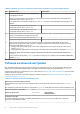
Таблица 3. Таблица начальной настройки (пустая) (продолжение) Cluster Name Сервисные коды устройств Сбой одного диска Введите сервисный код. Сервисный код указывается на бирке черного цвета на лицевой стороне базового шасси. При получении системы определите базовые шасси, которые вы хотите настроить в качестве кластера, и запишите их сервисные коды.
Таблица 3. Таблица начальной настройки (пустая) (продолжение) Сеть хранения Позволяет клиентам получать доступ к хранилищу в кластере. IP-адреса в сети хранения используются для целевых устройств iSCSI, инициаторов iSCSI и IP-адреса для глобального обнаружения хранилища. Для каждого устройства необходимо как минимум 6 IP-адресов Модель PowerStore X. Однако для повышения производительности настоятельно рекомендуется использовать не менее 8 IP-адресов для каждого устройства Модель PowerStore X.
Таблица 3. Таблица начальной настройки (пустая) (продолжение) Гипервизор Запишите свои существующие учетные данные администратора для входа в vCenter. Рабочий процесс начальной настройки автоматически создаст центр обработки данных и кластер ESXi и свяжет их с вашим кластером. ПРИМЕЧАНИЕ: Убедитесь, что сервер vCenter доступен в сети.
3 Модель PowerStore X: Требования к настройке сетей Эта глава включает следующую информацию. Темы: • • • • Требования и варианты подключения стоечного коммутатора верхнего уровня (ToR) Сети Модель PowerStore X Варианты виртуальных ЛС Модель PowerStore X IP-адреса для настройки сетей Требования и варианты подключения стоечного коммутатора верхнего уровня (ToR) PowerStore требуется возможность подключения к паре стоечных коммутаторов (ToR).
PowerStore Network Topology with Top of Rack Switches and MC-LAG Interconnect Upstream Switch 2 Upstream Switch 1 Port Channel Top of Rack Switch 1 Port 0 Top of Rack Switch 2 MC-LAG Interconnect Port 1 Port 1 Node A Port 0 Node B PowerStore T Appliance Legend: 10 Gb 1 Gb Рисунок 1.
ПРИМЕЧАНИЕ: Расположение портов для надежных восходящих каналов связи может отличаться в зависимости от поставщика коммутатора или модели. MC-LAG — это технология межсоединения коммутаторов, которая позволяет соединить несколько независимых стоечных коммутаторов верхнего уровня (ToR) с одним виртуальным шасси. MC-LAG позволяет группам портов агрегирования каналов связи (LAG) охватывать несколько шасси, обеспечивая лучшую отказоустойчивость LAG-подключения.
PowerStore Network Topology with a no MC-LAG interconnect Upstream Switch 2 Upstream Switch 1 Port Channels Top of Rack Switch 1 Port 0 Top of Rack Switch 2 Port 1 Port 1 Node A Port 0 Node B PowerStore T Appliance Legend: 10 Gb 1 Gb Рисунок 2.
ПРИМЕЧАНИЕ: Расположение портов для надежных восходящих каналов связи может отличаться в зависимости от поставщика коммутатора или модели. Для подключения L2 без MC-LAG требуются резервные высокоскоростные подключения.
Рисунок 4. Сетевой трафик Модель PowerStore X Убедитесь в том, что между интерфейсами Модель PowerStore X осуществляется обмен данными через виртуальные ЛС, приведенные выше. Чтобы проверить правильность маршрутизации всех данных на уровне L2 и/или L3 для всех используемых сетей, обратитесь к документации вашего поставщика сети Модель PowerStore X. Таблица 6. Сети Модель PowerStore X Сеть Типы трафика Транспортные порты узлов Начальное обнаружение с использованием утилиты обнаружения PowerStore.
Варианты виртуальных ЛС Модель PowerStore X В следующей таблице приведен пример различных типов сетей с примерами идентификаторов виртуальной ЛС в устройстве Модель PowerStore X. Таблица 7. Конфигурация виртуальной ЛС Модель PowerStore X Пример идентификатора виртуальной ЛС Сеть Порты виртуальной ЛС Пример подсети 1 Удаленное обнаружение (выполняется во встроенной виртуальной ЛС) Непомеченный 169.254.x.x/16 100 Управление Помеченный y.y.y.y/24 200 Хранилище Помеченный y.y.x.
Таблица 8.
4 Настройка с коммутаторами S4148-ON серии Dell EMC PowerSwitch Эта глава включает следующую информацию.
Таблица 9. Таблица подготовки к настройке сети (заполненная) (продолжение) Шаг Описание шага Примечания ● Порт 0 на узле A и порт 0 на узле B должны быть подключены к противоположным коммутаторам ● Порт 1 на узле A и порт 1 на узле B должны быть подключены к противоположным коммутаторам Запишите порты коммутаторов ToR для выполнения следующих подключений. Узел A, порт 0, к ToR 1, порт 1 Узел A, порт 1, к ToR 2, порт 1 Узел B, порт 0, к ToR 2, порт 54 Узел B, порт 1, к ToR 1, порт 54 3.
Таблица 9. Таблица подготовки к настройке сети (заполненная) (продолжение) Шаг 10. 11. Описание шага Примечания Приоритет VLT для коммутатора 1 1 Приоритет VLT для коммутатора 2 8192 Запишите порты на коммутаторах ToR, которые будут использоваться для подключения к восходящим каналам связи.
Информацию о требованиях к кабелю последовательного порта консоли и дополнительные сведения см. в руководстве по установке коммутатора Dell EMC PowerSwitch S4100-ON, расположенном по адресу: https://www.dell.com/support/ home/us/en/04/product-support/product/networking-s4148f-on/docs. Для настройки коммутаторов для развертывания необходимо создать терминальный сеанс для каждого из коммутаторов. 1. Включите коммутатор. 2.
Copyright (c) 1999-2018 by Dell Inc. All Rights Reserved. OS Version: 10.4.1.2 Build Version: 10.4.1.2.524 Build Time: 2018-09-26T17:20:01-0700 System Type: S4148F-ON Architecture: x86_64 Up Time: 2 weeks 04:34:35 3. Убедитесь, что на коммутаторе установлена лицензия. Выполните команду show license status , чтобы отобразить установленную лицензию. В поле License Type: должно быть указано следующее: PERPETUAL.
switchport access vlan 1 no shutdown 5. Настройте IP-адрес управления для коммутатора. ПРИМЕЧАНИЕ: В следующем примере команды предполагается, что для коммутатора активировано автоматическое назначение IP-адресов с помощью протокола динамической настройки хостов (DHCP). Если автоматическое назначение IP-адресов с помощью DHCP не активировано, не включайте no ip address dhcp в список команд, указанных ниже. interface mgmt 1/1/1 no shutdown no ip address dhcp ip address 100.0.100.
Коммутатор 1 Коммутатор 2 spanning-tree rstp priority [40960} exit Настройка Модель PowerStore X виртуальных ЛС на коммутаторе 1. Выполните терминальное подключение к коммутатору, а именно к первому коммутатору ToR (коммутатор 1) 2. Перейдите в режим глобальной настройки. configure terminal 3. Создайте внутреннюю сеть. interface vlan 1 description Internal_Network no shutdown exit 4. Создайте виртуальную ЛС для сети управления. interface vlan 100 description Management_Network no shutdown exit 5.
no shutdown exit Настройка объединения виртуальных каналов (VLTi) Выполните следующие шаги, если вы решили реализовать VLT для межсоединения уровня 2 двух коммутаторов ToR Dell EMC S4148-ON серии PowerSwitch. Для реализации VLTi необходимо обратиться к сетевому администратору. VLTi не следует настраивать без специалиста по работе с сетью. Можно соединить коммутаторы кабелем до настройки соединения между коммутаторами или сделать это после настройки типа соединения.
ПРИМЕЧАНИЕ: MAC-адрес VLT не может состоять только из нулей (00:00:00:00:00). vlt-mac 00:00:00:00:00:01 Используйте этот же MAC-адрес VLT при настройке коммутатора 2. 9. Повторите эти шаги для второго коммутатора. При этом поменяйте местами IP-адреса коммутаторов в шагах 1 и 5, как показано в приведенном ниже примере кода. Таблица 11.
no shutdown switchport mode trunk switchport access vlan 1 switchport trunk allowed vlan 100,200,400 flowcontrol receive off flowcontrol transmit off spanning-tree port type edge exit 5. Повторите действия по подключению коммутатора 2 к узлу A (порт 0) и узлу B (порт 1), как показано ниже. При настройке коммутатора 2 обратите внимание, что для интерфейсов Ethernet используется обратный порядок настройки.
4. Настройте на коммутаторе порты восходящего канала связи. ПРИМЕЧАНИЕ: Для iSCSI рекомендуется отключить управление потоком, как показано ниже. interface ethernet 1/1/29 description Uplink_Ports no shutdown channel-group 30 mode active no switchport flowcontrol receive off flowcontrol transmit off interface ethernet 1/1/30 description Uplink_Ports no shutdown channel-group 30 mode active no switchport flowcontrol receive off flowcontrol transmit off 5. Сохраните конфигурацию в NVRAM.
5 Модель PowerStore X: Подключение устройства к коммутаторам В этой главе содержится следующая информация. Темы: • • • Подсоедините базовое шасси к коммутаторам ToR Соединение ToR-коммутаторов между собой Подключение стоечных коммутаторов верхнего уровня к основным восходящим каналам связи Подсоедините базовое шасси к коммутаторам ToR Подсоедините узлы к стоечным коммутаторам верхнего уровня (ToR). 2 4 1 3 Рисунок 5.
Соединение ToR-коммутаторов между собой При двойном развертывании коммутаторов PowerStore с использованием VLT необходимо, чтобы два стоечных коммутатора верхнего уровня (ToR) были подключены друг к другу. 1 2 Рисунок 6. Подключение коммутатор-коммутатор Используйте два кабеля, поддерживающих соединение между высокоскоростными портами, например 100Gbps Direct Attached (DAC). Рекомендуется использовать порты с одинаковыми номерами для пары на верхнем и нижнем коммутаторах. Таблица 14.
Core uplinks Uplink A 1 3 Uplink B 4 2 Рисунок 7. Подключение стоечного коммутатора верхнего уровня (ToR) S4148-ON серии Dell EMC PowerSwitch к основным восходящим каналам связи Таблица 15. Действия для подключения коммутаторов ToR Dell EMC S4148-ON серии PowerSwitch к основным восходящим каналам связи 1 Подключите порт 30 нижнего коммутатора ToR к основному восходящему каналу связи A. 2 Подключите порт 29 нижнего коммутатора ToR к основному восходящему каналу связи B.
6 Проверка настройки коммутатора и сети В этой главе содержится следующая информация. Темы: • • Проверка конфигурации стоечных коммутаторов верхнего уровня (ToR) Средство проверки сети для PowerStore Проверка конфигурации стоечных коммутаторов верхнего уровня (ToR) После настройки и подключения коммутаторов ToR Dell EMC S4148-ON серии PowerSwitch проверьте конфигурацию, прежде чем выполнять обнаружение развертывания модели Модель PowerStore X. 1. Создание сеанса терминала с коммутатором. 2.
400 Active 4094 Inactive vMotion_Network T Eth1/1/1,1/1/54 T Po30 T Po1000 5.
No mismatch VLT VLAN mismatch: No mismatch 9. Проверьте конфигурацию порта VLT. show vlt vlt-port-detail vlt-port-channel ID : 30 VLT Unit ID Port-Channel Status Configured ports Active ports ------------------------------------------------------------------------------1 port-channel30 up 2 2 * 2 port-channel30 up 2 2 10. Проверьте текущую конфигурацию коммутатора ToR 1 и выполните аналогичные проверочные действия для коммутатора ToR 2.
7 Обнаружение устройств PowerStore После настройки сетей и установки устройств можно приступить к обнаружению устройства PowerStore и начать процесс начальной настройки. Темы: • • Обнаружение при прямом подключении Обнаружение при удаленном подключении Обнаружение при прямом подключении Это рекомендуемая процедура, которая подразумевает ваше обязательное присутствие в центре обработки данных или лаборатории, где установлено базовое шасси.
Обнаружение при удаленном подключении Network Node Если у вас нет доступа к базовому шасси, разверните рабочую станцию или виртуальную машину в той же сети, где находится система PowerStore, и используйте PowerStore утилиту обнаружения для обнаружения и создания кластера. B A Рисунок 9.
Перед обнаружением одного из статических IP-адресов, зарезервированных для обнаружения PowerStore, ознакомьтесь со следующими замечаниями. ● Скачайте и запустите Средство проверки сети (NVT) PowerStore, чтобы проверить правильность конфигурирования сетей. NVT можно скачать на странице Dell EMC Central Solutions по адресу https://psapps.emc.com/central/solution/NVTPowerStore.
8 Начальная настройка устройства Модель PowerStore X В этой главе содержится следующая информация. Темы: • • Мастер начальной настройки Получение заполненной таблицы начальной настройки Мастер начальной настройки После обнаружения устройства Модель PowerStore X, вы будете перенаправлены в Initial Configuration Wizard (ICW) для настройки сетей на устройстве Модель PowerStore X.
○ ○ ○ ○ ○ Виртуальные тома Конечные точки протокола Поставщик VASA Контейнеры хранилища Управление хранилищем на основе политик Подробнее см. в разделе Руководство по инфраструктуре виртуализации PowerStore. После начальной настройки устройства Модель PowerStore X вы можете добавить дополнительные сети хранения, как описано в разделе: Создание дополнительной сети хранения.
Таблица 16. Таблица начальной настройки (заполненная) (продолжение) данных. Одноуровневая отказоустойчивость накопителя соответствует требованиям к доступности для всех типов дисков и точек емкости. Но двойная отказоустойчивость накопителя может обеспечить более высокую устойчивость и защиту.
Таблица 16. Таблица начальной настройки (заполненная) (продолжение) Рекомендуется выбрать создание этого IP-адреса. Он используется в качестве единого плавающего IP-адреса с высокой доступностью для хостов для удобного обнаружения ресурсов хранения данных в кластере. Если вы выбрали настройку Global Storage Discovery IP address, то последний IPадрес, указанный для сети хранения, будет использоваться в качестве Global Storage Discovery IP address.
Таблица 16. Таблица начальной настройки (заполненная) (продолжение) Учетные данные администратора устройства Модель PowerStore X Введите учетные данные администратора устройства Модель PowerStore X для vCenter, чтобы получить доступ к устройству Модель PowerStore X. Имя пользователя администратора Администратор по умолчанию Password — это указанный пользователем пароль, предоставляемый после первого входа на устройстве Модель PowerStore X.
A Расширение сети хранения для работы на нескольких портах В приложении содержится следующая информация. Темы: • Расширение сети хранения Расширение сети хранения Сеть хранения можно расширить для работы на нескольких портах устройства Модель PowerStore X. Для выполнения шагов по расширению сети хранения вам потребуется следующая информация.
Таблица 17. Ресурсы сети хранения (продолжение) Сетевой ресурс Пример целевого объекта iSCSI узла A, а другой для целевого объекта iSCSI узла B. Таблица 18.
2 1 Рисунок 10. Подключение дополнительного порта 1. Подключите порт 2 нижнего узла (A) к порту 2 нижнего коммутатора (1). 2. Подключите порт 2 верхнего узла (B) к порту 53 верхнего коммутатора (2). Настройка сети VLAN на стоечных коммутаторах верхнего уровня Ниже приведен пример настройки сетей VLAN на двух стоечных коммутаторах верхнего уровня (ToR) S4148 серии Dell PowerSwitch. Вы можете подключить узлы устройства Модель PowerStore X к коммутаторам до или после выполнения этих шагов.
no shutdown exit 4. Повторите шаги 1–3 для порта 53 на коммутаторе ToR 2. Таблица 19.
B Создание дополнительной сети хранения В этом приложении содержится следующая информация. Темы: • Создание новой сети хранения Создание новой сети хранения Вы можете настроить до 32 сетей хранения — не более 8 сетей на один порт платы с 4 портами. Для каждого порта платы с 4 портами можно настроить до 8 сетей хранения. Для выполнения шагов по созданию новой сети хранения вам потребуется следующая информация.
Таблица 20. Ресурсы новой сети хранения (продолжение) Сетевой ресурс Пример Если вы выбрали IP-адрес глобального обнаружения хранилища, вам потребуется не менее 7 (а лучше 9) IPадресов для каждого устройства. Таблица 21.
2 1 Рисунок 11. Подключение дополнительного порта 1. Подключите порт 2 нижнего узла (A) к порту 2 нижнего коммутатора (1). 2. Подключите порт 2 верхнего узла (B) к порту 53 верхнего коммутатора (2). Настройка сети хранения на коммутаторах ToR Ниже приведен пример настройки сети хранения на двух стоечных коммутаторах верхнего уровня (ToR) S4148 серии Dell PowerSwitch. Вы можете подключить узлы устройства Модель PowerStore T к коммутаторам до или после выполнения этих шагов. Пошаговые инструкции см.
switchport trunk allowed vlan 210 no shutdown 5. Повторите шаг 1 для порта 53 на коммутаторе ToR 2. Таблица 22.
C Другие операции по настройке коммутатора Dell EMC S4148-ON серии PowerSwitch Это приложение включает следующую информацию. Темы: • • Восстановление заводских настроек коммутатора Текущая конфигурация коммутаторов ToR Dell EMC S4148-ON серии PowerSwitch Восстановление заводских настроек коммутатора При необходимости вы можете выполнить сброс настроек коммутаторов Dell EMC S4148-ON серии PowerSwitch до заводских значений по умолчанию.
Таблица 23. Пример текущей конфигурации стоечных коммутаторов верхнего уровня (ToR) Коммутатор 1 ! snmp-server contact http://www.dell.com/ support hostname Switch1 interface breakout 1/1/25 map 100g-1x interface breakout 1/1/26 map 100g-1x interface breakout 1/1/29 map 100g-1x interface breakout 1/1/30 map 100g-1x username admin password $6$q9QBeYjZ$jfxzVqGhkxX3smxJSH9DDz7/3OJc6m5w jF8nnLD7/VKx8SloIhp4NoGZs0I/ UNwh8WVuxwfd9q4pWIgNs5BKH. role sysadmin ntp server 100.0.10.
Таблица 23.
Таблица 23.
Таблица 23.
Таблица 23.
Таблица 23.