Dell EMC PowerStore Network Planning Guide 1.0 May 2020 Rev.
Notes, cautions, and warnings NOTE: A NOTE indicates important information that helps you make better use of your product. CAUTION: A CAUTION indicates either potential damage to hardware or loss of data and tells you how to avoid the problem. WARNING: A WARNING indicates a potential for property damage, personal injury, or death. © 2020 Dell Inc. or its subsidiaries. All rights reserved. Dell, EMC, and other trademarks are trademarks of Dell Inc. or its subsidiaries.
Contents Additional Resources...................................................................................................................... 5 1 PowerStore models and network hardware overview....................................................................... 6 Using this guide......................................................................................................................................................................6 PowerStore deployment models...........................
B PowerStore Network Setup Preparation Worksheets.................................................................... 30 PowerStore T model: Network Setup Preparation Worksheet (blank)....................................................................... 30 PowerStore T model: example of completed Network Setup Preparation Worksheet............................................. 32 PowerStore X model Network Setup Preparation Worksheet (blank)..................................................................
Preface Additional Resources As part of an improvement effort, revisions of the software and hardware are periodically released. Some functions that are described in this document are not supported by all versions of the software or hardware currently in use. The product release notes provide the most up-to-date information about product features. Contact your technical support professional if a product does not function properly or does not function as described in this document.
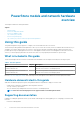
1 PowerStore models and network hardware overview This chapter includes the following information. Topics: • • • • • • Using this guide PowerStore deployment models PowerStore appliance nodes Top-of-Rack (ToR) switches PowerStore logical topology Top-of-Rack (ToR) switch connectivity options and requirements Using this guide This guide is designed to help you prepare to configure your switches and networks for PowerStore.
• PowerStore Hardware Information Guide PowerStore deployment models The different PowerStore models support different types of storage. Table 2. PowerStore deployment models Deployment Model numbers Supported configuration Refer to PowerStore T model appliance • • • • • 1000T 3000T 5000T 7000T 9000T Supports block (Storage Area Network (SAN)), file (Network Attached Storage (NAS)), and Virtual Volume (vVol) workloads with the software stack deployed directly on the bare metal of the system.
NOTE: The examples used in this guide describe how to cable port 0 and port 1 of the 4 port card on the base enclosure nodes. See the PowerStore Clustering and High Availability White Paper for specific steps to add more ports to provide additional bandwidth and fault tolerance. Top-of-Rack (ToR) switches PowerStore requires connectivity to a pair of Top-of-Rack (ToR) switches to ensure high availability.
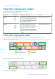
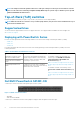
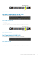
Serial Console Port Management Port Figure 4. S4000 series PSU-side Dell EMC PowerSwitch S4148T-ON Connectivity to PowerStore nodes is through the ports on the I/O panel. Figure 5. S4148T-ON switch I/O-side • • 48x10 GBASE-T 4x10/25/40/50/100GbE Connectivity to S4000 series switches from a jumpbox or laptop is done through the serial console port. Serial Console Port Management Port Figure 6.
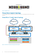
Management Port Serial Console Port Figure 8. S5248 PSU-side PowerStore logical topology The following diagrams demonstrate the logical network topology for a PowerStore T model deployment, and a PowerStore X model deployment. PowerStore T model logical topology Management ToR 1 Embedded module Production ToR 2 Embedded module PowerStore T base enclosure Management VLANS or Subnets Production VLANS or Subnets Remote Discovery Storage Management NAS Internal Figure 9.
PowerStore X model logical topology Management Production ToR 1 ToR 2 Embedded module Embedded module PowerStore X base enclosure Management VLANS or Subnets Production VLANS or Subnets Remote Discovery Storage Management vMotion Internal Figure 10. PowerStore X model logical topology and network paths Top-of-Rack (ToR) switch connectivity options and requirements PowerStore requires connectivity to a pair of Top-of-Rack (ToR) switches.
Switch to switch (L2) connectivity options It is recommended to use one of the following options to connect the switches together. Table 4. Switch to switch interconnect options Switch interconnect options Recommendation 1. Multi-chassis Link Aggregation Group (MC-LAG) Dell highly recommends using MC-LAG for connectivity between the switches. 2. Reliable L2 uplinks If MC-LAG is not an option, then the next best recommended connectivity between the switches is to use reliable L2 uplinks.
Table 5. Vendor specific MC-LAG technology(continued) Vendor Proprietary MC-LAG technology Cisco Virtual PortChannel (vPC) Brocade Multi-Chassis Trunking (MCT) NOTE: Refer to your vendor's documentation to determine their technology for MC-LAG. MC-LAG connectivity requirements are: • • • A minimum of two connection cables in parallel with a high speed reliable connection. Connections must be made through the high speed ports on the switch.
Node to Top-of-Rack (ToR) switch connectivity requirements A dual switch topology requires that each of the base enclosure appliance nodes have at least one connection to each of the Top-of-Rack (ToR) switches to provide redundancy at the NIC and switch levels. Figure 13.
I PowerStore T model: Network Planning Topics: • • • PowerStore T model out-of-band management switch PowerStore T model: Network configuration requirements Prepare to configure the networks PowerStore T model: Network Planning 15
2 PowerStore T model out-of-band management switch This chapter includes the following information. Topics: • PowerStore T model out-of-band management switch connectivity PowerStore T model out-of-band management switch connectivity In addition to the two Top-of-Rack (ToR) switches required for all PowerStore T model deployments, connectivity to an out-of-band (OOB) management switch is required for system management and discovery.
Layer 3 – Management Uplinks Management Management Uplink A Uplink B Port Channel Layer 3 – OOB Management Switch Figure 15.
3 PowerStore T model: Network configuration requirements This chapter includes the following information. Topics: • • • PowerStore T model appliance networks PowerStore T model network VLAN requirements IP address requirements for initial configuration PowerStore T model appliance networks PowerStore T model requires all networks to be unique. It is highly recommended to deploy PowerStore T model with multiple and unique VLANs to separate the traffic.
Ensure that the PowerStore T model system interfaces are able to communicate to each other through the VLANs shown above. Consult your network vendor documents to ensure all proper L2 and/or L3 traffic is being routed properly for all networks that PowerStore T model is utilizing. Table 6.
PowerStore T model network VLAN requirements The following table shows an example of the different type of networks with sample VLAN IDs in a PowerStore T model appliance. Table 7. PowerStore T model VLAN configuration Sample VLAN ID Network Switch used VLAN Ports Subnet 100 Remote Discovery (runs over the Native VLAN) Out-of-band management Untagged 169.254.x.x/16 100 Management Out-of-band management Untagged y.y.y.y/24 200 Storage Top-of-rack (ToR) switch Tagged y.y.x.
Table 8. PowerStore T model IP address requirements(continued) Network IP Addresses Required Grand total required per Appliance for Management and Storage 5 Grand total for a Single Appliance Cluster 7 You can choose to assign either IPv4 or IPv6 addresses to the management, or storage networks. You cannot assign different IP versions to the same network, for example, all 4 IPs assigned to the management network must all be either IPv4 or IPv6.
4 Prepare to configure the networks This chapter contains the following information. Topics: • Preparing to configure PowerStore Preparing to configure PowerStore Prior to deployment work with your network administrator to reserve the network resources required for deployment. Blank worksheets have been provided in this document to assist you with reserving network resources.
II PowerStore X model: Network Planning Topics: • • PowerStore X model: Network configuration requirements Prepare to configure the networks PowerStore X model: Network Planning 23
5 PowerStore X model: Network configuration requirements This chapter includes the following information. Topics: • • • PowerStore X model networks PowerStore X model networks VLAN options IP addresses for network configuration PowerStore X model networks PowerStore X modelrequires all networks to be unique. It is highly recommended to deploy PowerStore X model with multiple and unique VLANs to separate the traffic.
Ensure that the PowerStore X model interfaces are able to communicate to each other through the VLANs shown above. Consult your network vendor documents to ensure all proper L2 and/or L3 traffic is being routed properly for all networks that PowerStore X model is utilizing. Table 9. PowerStore X model networks Network Types of traffic Node transport ports Initial discovery using the PowerStore Discovery Utility.
IP addresses for network configuration You will need IP addresses to configure the networks in PowerStore X model through the Initial Configuration Wizard (ICW) which runs automatically after you discover PowerStore X model. Table 11.
6 Prepare to configure the networks This chapter contains the following information. Topics: • Preparing to configure PowerStore Preparing to configure PowerStore Prior to deployment work with your network administrator to reserve the network resources required for deployment. Blank worksheets have been provided in this document to assist you with reserving network resources.
A Discovering PowerStore Appliances Once you have configured your networks and completed installing the appliances, you can discover your PowerStore appliance and begin the initial configuration process. Topics: • Discover your system Discover your system Once you have completed installing your base enclosure and optional expansion enclosures, discover your newly installed enclosure, and then create a cluster.
Discovery with remote connection Network Node If you do not have access to the base enclosure, deploy a workstation or virtual machine on the same network as the PowerStore system and use the PowerStore Discovery Utility to discover and create a cluster. B A Network Node Figure 18. PowerStore T model B A Figure 19. PowerStore X model • • • • • (Optional) Download and run the Network Validation Tool (NVT) for PowerStore to validate that your networks are correctly configured.
B PowerStore Network Setup Preparation Worksheets This appendix includes the following information.
Table 12. PowerStore T model Network Setup Preparation Worksheet (blank)(continued) Step Step details Notes Management Uplink B to 7. Record the VLAN IDs that will be used on the OOB management switch: Remote Discovery (untagged) Management (untagged) 8. Record the VLAN IDs that will be used on the Top-of-Rack (ToR) switches: Storage network (tagged) NAS (tagged) Internal (untagged) 9.
Table 12. PowerStore T model Network Setup Preparation Worksheet (blank)(continued) Step Step details Notes Uplink B to ToR 2 15. Record the port channel ID used for connectivity between the ToR switches and the uplinks. If deploying with MC-LAG, enter the port channel ID used for the uplink. Only a single port channel ID is required for MC-LAG. Alternatively, record the uplink port channel IDs required for Reliable L2. Reliable L2 connectivity requires two port channel IDs. 1.
Table 13. PowerStore T model Network Setup Preparation Worksheet (example)(continued) Step 4. Step details Notes Node B, Port 0 to ToR 2 port 54 Node B, Port 1 to ToR 1 port 54 Record the out-of-band management switch ports to connect to: Node A management 1GbE port to OOB port 2 Node B management 1GbE port to OOB port 53 5. Optionally, record the port on the out-of-band (OOB) management switch port to use for remote discovery. OOB port 1 6.
Table 13. PowerStore T model Network Setup Preparation Worksheet (example)(continued) Step 13. 14. 15. Step details Notes VLT priority for switch 2 8192 If configuring with Link Aggregation Control Protocol (LACP) record the LACP (port channel) ID for the node connections: Port Channel ID for Node A port channel 10 Port Channel ID for Node B port channel 20 Record the ports on the ToR switches that will be used to connect to the uplinks.
Table 14. PowerStore X model Network Setup Preparation Worksheet (blank)(continued) Step Step details Notes 2. Print out the Initial Configuration Worksheet to record the additional network resources you will need to create networks in PowerStore X model the first time you create a cluster. 3. Determine which of the Top-of-Rack (ToR) switch ports will be connected to the PowerStore X model appliance base enclosure nodes. At a minimum, ports 0 and 1 on the node must be connected to the ToR switches.
Table 14. PowerStore X model Network Setup Preparation Worksheet (blank)(continued) Step Step details Notes NOTE: You cannot use all zeros (00:00:00:00:00) for the VLT MAC address. VLT priority for switch 1 VLT priority for switch 2 11. Record the ports on the ToR switches that will be used to connect to the uplinks. Uplink A to ToR 1 Uplink B to ToR 1 Uplink A to ToR 2 Uplink B to ToR 2 12. Record the port channel ID using for connectivity between the ToR switches, and the uplinks.
Table 15. PowerStore X model Network Setup Preparation Worksheet completed example(continued) Step Step details Notes 3. Determine which of the Top-of-Rack (ToR) switch ports will be connected to the PowerStore X model appliance base enclosure nodes. At a minimum, ports 0 and 1 on the node must be connected to the ToR switches.
Table 15. PowerStore X model Network Setup Preparation Worksheet completed example(continued) Step 11. 12. Step details Notes VLT priority for switch 1 1 VLT priority for switch 2 8192 Record the ports on the ToR switches that will be used to connect to the uplinks. Uplink A to ToR 1 port 29 Uplink B to ToR 1 port 30 Uplink A to ToR 2 port 29 Uplink B to ToR 2 port 30 Record the port channel ID using for connectivity between the ToR switches, and the uplinks.
C PowerStore Initial Configuration Worksheets This appendix includes the following information.
Table 16. Initial Configuration Worksheet (blank)(continued) Management Network Connects the cluster to services such as DNS and NTP. The IP addresses in the management network are used to address the cluster, appliances, controllers, and internal hosts. VLAN Netmask/Prefix Length Gateway 3 IPs for each PowerStore T model Appliance 5 IPs for each PowerStore X model Appliance IP Addresses (Optional, Defaults to 0) Storage Network (Optional) Enables clients to access the storage in the cluster.
Table 16. Initial Configuration Worksheet (blank)(continued) Protocol (SSH/SNMP) IP Address Port User Credentials / Community String PowerStore T model Only Out-of-Band Management Switch Information (Optional) You can provide read-only credentials for the switches. Protocol (SSH / SNMP) IP Address Port User Credentials / Community String PowerStore X model Only Hypervisor Record your existing vCenter administrator login credentials.
Table 17. PowerStore T model: completed example of an Initial Configuration Worksheet(continued) Use the following default user credentials when you log in to the PowerStore Manager for the first time. Default Username admin Default Password Password123# Cluster Details For resource management, efficiency, and availability purposes, appliances act as a single component called cluster.
Table 17. PowerStore T model: completed example of an Initial Configuration Worksheet(continued) vMotion Network Enables users to migrate virtual machines within the vSphere cluster. The IP addresses in the vMotion network are used for a dedicated network that transfer virtual machines between appliances.
Table 17. PowerStore T model: completed example of an Initial Configuration Worksheet(continued) Gateway or Proxy Server Port N/A Proxy Server User Credentials N/A (Not applicable for Gateway Connect) Policy Manager IP Address and Port N/A (Not applicable for Direct Connect without remote access or Gateway Connect) PowerStore X model: example of a completed Initial Configuration Worksheet The following is an example of an Initial Configuration Worksheet completed for a PowerStore T model deployment.
Table 18. PowerStore X model: completed example of an Initial Configuration Worksheet (continued) Storage Network (Optional) Enables clients to access the storage in the cluster. The IP addresses in the storage network are used for iSCSI targets, iSCSI initiators, and the Global Storage Discovery IP address. If you want to enable iSCSI interfaces later or only use Fibre Channel, you can skip this step. NOTE: At a minimum, you need 6 IP addresses for each PowerStore X model appliance.
Table 18. PowerStore X model: completed example of an Initial Configuration Worksheet (continued) PowerStore X model Only Hypervisor Record your existing vCenter administrator login credentials. The initial configuration workflow automatically creates a datacenter and ESXi cluster, and associates them with your cluster. NOTE: Ensure that the vCenter Server is accessible on the network. Existing vCenter IP Address 100.0.100.220 Existing vCenter User Credentials administrator@vsphere.