
Setup Guide


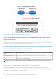

Table 13. Network Setup Preparation Worksheet for deployments with ToR switches (blank) (continued)
Step Step details Notes
6. Record the ports on the OOB management switch that will be used to connect to the uplinks.
Management Uplink A to
Management Uplink B to
7. Record the VLAN IDs that will be used on the OOB management switch:
Remote Discovery (untagged)
Management (untagged)
8. Record the VLAN IDs that will be used on the Top-of-Rack (ToR) switches:
Storage network (tagged)
Internal (untagged)
NAS (tagged) (for Unified deployments only)
9. Reserve and record the IP addresses necessary to configure the switch below:
Management IP address for out-of-band management
switch
Management IP address for switch 1
Management IP address for switch 2
Default gateway
NTP server
10. Dell EMC supports deploying PowerStore T model with two Top-of-Rack (ToR) switches with a layer 2 interconnect
link.
Choose which type of layer 2 interconnect you will use:
Highly Recommended: Multi-chassis Link Aggregation Group (MC-LAG)
If you will be using MC-LAG, record the ports you will use to connect the switches together.
Switch to switch port pair 1
Switch to switch port pair 2
Alternatively, L2 Uplinks without MC-LAG
11. If using MC-LAG, enter the Domain ID.
12. If using VLT for the Layer 2 interconnect, record the:
VLT MAC address to use for both switch 1 and switch 2.
Use the same VLT MAC address for switch 1 and switch
2.
NOTE: You cannot use all zeros
(00:00:00:00:00) for the VLT MAC address.
VLT priority for switch 1
VLT priority for switch 2
13. If configuring with Link Aggregation Control Protocol (LACP) record the LACP (port channel) ID for the node
connections:
Port Channel ID for Node A
Port Channel ID for Node B
14. Record the ports on the ToR switches that will be used to connect to the uplinks.
Prepare to configure the switches and networks for deployment 37