
Setup Guide


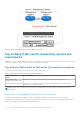

Table 13. Network Setup Preparation Worksheet for deployments with ToR switches (blank) (continued)
Step Step details Notes
Uplink A to ToR 1
Uplink B to ToR 1
Uplink A to ToR 2
Uplink B to ToR 2
15. Record the port channel ID used for connectivity between the ToR switches and the uplinks.
If deploying with MC-LAG, enter the port channel ID used
for the uplink.
Only a single port channel ID is required for MC-LAG.
Alternatively, record the uplink port channel IDs required for L2 Uplinks without MC-LAG.
L2 Uplinks without MC-LAG connectivity requires two port channel IDs.
1. Port channel ID for L2 Uplinks without MC-LAG
2. Port channel ID for L2 Uplinks without MC-LAG
16. As a best practice it is recommended to add a spanning tree protocol to the ToR switches. Record the spanning tree
protocols to set on each switch.
Spanning tree protocol for ToR switch 1
Spanning tree protocol for ToR switch 2
17. Once you have completed steps above, you have the necessary information to configure the switches. Continue to
work with your network administrator to complete the Initial Configuration Worksheet now to ensure that:
● Your network configuration on the switch aligns with the network configuration that will be done in PowerStore T
model.
● You reserve the necessary network resources to complete deployment of PowerStore T model and the PowerStore
T model networks.
18. Determine if you will use a direct connection or a remote connection to discover your PowerStore.
Once you have successfully discovered your PowerStore, you will be guided through the Initial Configuration Wizard
to create your first PowerStore cluster.
38 Prepare to configure the switches and networks for deployment