
Setup Guide
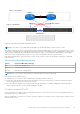
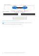
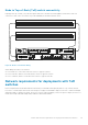


Table 19. Network Setup Preparation Worksheet for deployments with ToR switches (completed)
Step Step details Notes
1. Print this table to record the reserved resources.
2. Print out the Initial Configuration Worksheet to record the additional network resources you will need to create
networks in PowerStore T model the first time you create a cluster.
3. Determine which of the Top-of-Rack (ToR) switch ports will be connected to the PowerStore T model appliance base
enclosure nodes.
At a minimum, ports 0 and 1 on the node must be connected to the ToR switches. When cabling the nodes to the ToR
switches:
● Port 0 and Port 1 on the same node must connect to opposite switches
● Port 0 on Node A, and Port 0 on Node B must connect to opposite switches
● Port 1 on Node A, and Port 1 on Node B must connect to opposite switches
Record the ToR switch ports required to connect to:
Node A, Port 0 to ToR 1 port 1
Node A, Port 1 to ToR 2 port 1
Node B, Port 0 to ToR 2 port 54
Node B, Port 1 to ToR 1 port 54
4. Record the out-of-band management switch ports to connect to:
Node A management 1GbE port to OOB port 2
Node B management 1GbE port to OOB port 53
5. Optionally, record the port on the out-of-band (OOB)
management switch port to use for remote discovery.
OOB port 1
6. Record the ports on the OOB management switch that will be used to connect to the uplinks.
Management Uplink A to port 25
Management Uplink B to port 26
7. Record the VLAN IDs that will be used on the OOB management switch:
Remote Discovery (untagged) 100
Management (untagged) 100
8. Record the VLAN IDs that will be used on the Top-of-Rack (ToR) switches:
Storage network (tagged) 200
Internal (untagged) 1
NAS (tagged) (for Unified deployments only) 300
9. Reserve and record the IP addresses necessary to configure the switch below:
Management IP address for out-of-band management
switch
100.0.100.50/24
Management IP address for switch 1 100.0.100.10/24
Management IP address for switch 2 100.0.100.11/24
Default gateway 100.0.100.1
NTP server 100.0.100.200
10. Dell EMC supports deploying PowerStore T model with two Top-of-Rack (ToR) switches with a layer 2 interconnect
link.
Choose which type of layer 2 interconnect you will use:
48 Configuring Dell PowerSwitch Series for deployments with ToR switches