
Setup Guide
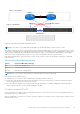
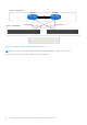


Table 19. Network Setup Preparation Worksheet for deployments with ToR switches
(completed) (continued)
Step Step details Notes
Highly Recommended: Multi-chassis Link Aggregation Group (MC-LAG)
If you will be using MC-LAG, record the ports you will use to connect the switches together.
Switch to switch port pair 1 25 to 25
Switch to switch port pair 2 26 to 26
Alternatively, L2 Uplinks without MC-LAG N/A
11. If using MC-LAG, enter the Domain ID. VLT domain ID 1
12. If using VLT for the Layer 2 interconnect, record the:
VLT MAC address to use for both switch 1 and switch 2.
Use the same VLT MAC address for switch 1 and switch
2.
NOTE: You cannot use all zeros
(00:00:00:00:00) for the VLT MAC address.
00:00:00:00:00:01
VLT priority for switch 1 1
VLT priority for switch 2 8192
13. If configuring with Link Aggregation Control Protocol (LACP) record the LACP (port channel) ID for the node
connections:
Port Channel ID for Node A port channel 10
Port Channel ID for Node B port channel 20
14. Record the ports on the ToR switches that will be used to connect to the uplinks.
Uplink A to ToR 1 port 29
Uplink B to ToR 1 port 30
Uplink A to ToR 2 port 29
Uplink B to ToR 2 port 30
15. Record the port channel ID using for connectivity between the ToR switches and the uplinks.
If deploying with MC-LAG, enter the port channel ID used
for the uplink.
Only a single port channel ID is required for MC-LAG.
port channel 30
Alternatively, record the uplink port channel IDs required for L2 Uplinks without MC-LAG.
L2 Uplinks without MC-LAG connectivity requires two port channel IDs.
1. Port channel ID for L2 Uplinks without MC-LAG N/A
2. Port channel ID for L2 Uplinks without MC-LAG N/A
16. As a best practice it is recommended to add a spanning tree protocol to the ToR switches. Record the spanning tree
protocols to set on each switch.
Spanning tree protocol for ToR switch 1 40960
Spanning tree protocol for ToR switch 2 45056
17 Record the port channel ID for the OOB management
switch.
port channel 10
18. Once you have completed steps above, you have the necessary information to configure the switches. Continue to
work with your network administrator to complete the Initial Configuration Worksheet now to ensure that:
Configuring Dell PowerSwitch Series for deployments with ToR switches 49