
Setup Guide


● Different rstp priority values should be used when configuring switch 1 and switch 2.
● 0 priority is typically reserved for the root bridge.
9. Repeat the above steps for the second switch (Switch2).
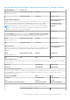
Switch1 Switch2
configure terminal
hostname Switch1
interface mgmt 1/1/1
no shutdown
no ip address dhcp
ip address 100.0.100.10/24
exit
management route 0.0.0.0/0 100.0.100.1
ntp server 100.0.100.200
spanning-tree mode rstp
spanning-tree rstp priority 40960
exit
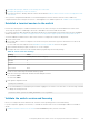
configure terminal
hostname Switch2
interface mgmt 1/1/1
no shutdown
no ip address dhcp
ip address 100.0.100.11/24
exit
management route 0.0.0.0/0 100.0.100.1
ntp server 100.0.100.200
spanning-tree mode rstp
spanning-tree rstp priority 45056
exit
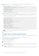
Configure PowerStore T model production VLANs on the switch
NOTE: Remote Discovery, and management VLANs are configured on the out-of-band management switch.
1. Establish a terminal connection to the first ToR switch (Switch1).
2. Enter global configuration mode.
configure terminal
3. Create the Internal network.
interface vlan 1
description Internal_Network
no shutdown
exit
4. Create the Storage VLAN.
interface vlan 200
description Storage_Network
no shutdown
exit
5. Create the NAS VLAN.
interface vlan 300
description NAS_Network
no shutdown
exit
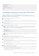
6. Repeat steps on the second ToR switch (Switch2).
configure terminal
interface vlan 1
description Internal_Network
no shutdown
exit
58
Configuring Dell PowerSwitch Series for deployments with ToR switches