
Setup Guide


NOTE: You cannot use all zeros (00:00:00:00:00) for the VLT MAC address.
vlt-mac 00:00:00:00:00:01
Use the same VLT MAC address when configuring switch 2.
9. Repeat above steps for the second switch.
While doing so, reverse the switch IP address in step 5 as demonstrated in the code sample below.
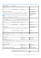
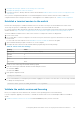
Table 22. Code sample of VLTi configuration steps
Switch 1 Switch 2
configure terminal
interface range ethernet 1/1/25-1/1/26
description vlti
no switchport
exit
vlt-domain 1
discovery-interface ethernet
1/1/25-1/1/26
backup destination 100.0.100.11
peer-routing
primary-priority 1
vlt-mac 00:00:00:00:00:01
configure terminal
interface range ethernet 1/1/25-1/1/26
description vlti
no switchport
exit
vlt-domain 1
discovery-interface ethernet
1/1/25-1/1/26
backup destination 100.0.100.10
peer-routing
primary-priority 8192
vlt-mac 00:00:00:00:00:01
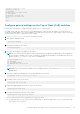
Configure the LACP port channels on the switch ports for the
nodes
Configuring LACP is not required, but highly recommended. The first 2 ports of the 4-Port Card are aggregated in an LACP
bond. The ports run in an active/active mode if LACP is configured. If LACP is not set, the ports run in active/passive mode.
LACP requires that a Virtual Link Trunking interconnect (VLTi) has been configured on the switches. See Configure Virtual Link
Trunking interconnect for details.
1. Establish a terminal connection to the first ToR switch (Switch1).
2. Enter global configuration mode.
configure terminal
3. Create VLT port-channel for Node A ports.
interface port-channel 10
description "LACP port channel for Node A"
vlt-port-channel 10
4. Configure allowed VLANs (VLAN trunking) and the native VLAN for Node A ports and ToR Switch 1.
no shutdown
switchport mode trunk
switchport access vlan 1
switchport trunk allowed vlan 200,300
5. Configure the ports that are connected to PowerStore T model nodes as spanning tree protocol (STP) edge ports.
spanning-tree port type edge
exit
60
Configuring Dell PowerSwitch Series for deployments with ToR switches