
Setup Guide


Cable the base enclosure to the ToR switches
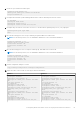
Cable the nodes to the Top of Rack (ToR) switches.
2
4
1 3
Figure 22. Base enclosure connection to the ToR switches
As demonstrated in the diagram, when cabling the nodes to the ToR switches:
● Port 0 and Port 1 on the same node must connect to opposite switches
● Port 0 on Node A, and Port 0 on Node B must connect to opposite switches
● Port 1 on Node A, and Port 1 on Node B must connect to opposite switches
Table 25. Steps to cable to the switches
1 Connect Port 0 of the bottom node (A) to Port 1 of the bottom switch (1).
2 Connect Port 1 of the bottom node (A) to Port 1 of the top switch (2).
3 Connect Port 1 of the top node (B), to Port 54 of the bottom switch (1).
4 Connect Port 0 of the top node (B), to Port 54 of the top switch (2).
Cable the ToR switches together
PowerStore dual switch deployments with VLT, requires that the two Top of Rack (ToR) switches are cabled together.
2
1
Figure 23. Switch-to-switch connectivity
66
Cable Dell PowerSwitch Series for deployments with ToR switches