
Setup Guide


PowerStore T model hardware overview
This chapter contains the following information.
Topics:
• PowerStore appliance nodes
• Supported switches
PowerStore appliance nodes
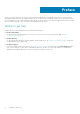
PowerStore appliances are deployed with a minimum of one base enclosure. Each base enclosure consists of two nodes.
A base enclosure consists of two nodes. Node A is the bottom node and Node B is the top node (flipped upside down in
enclosure). The port layouts on both nodes are the same.
1
2
3
4
4
4
4
2
3
1
2
4-port card
Management ports
Service ports
I/O Module
1 3
4
Figure 1. PowerStore base enclosure nodes and ports
0
1
2
3
0
1
2
3
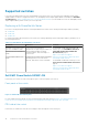
Figure 2. 4-Port card port numbers
NOTE:
The examples used in this guide describe how to cable port 0 and port 1 of the 4 port card on the base enclosure
nodes. See the PowerStore Clustering and High Availability White Paper for specific steps to add more ports to provide
additional bandwidth and fault tolerance.
2
PowerStore T model hardware overview 9