Dell Campus Networking Interoperability with Cisco Catalyst 1.
Revisions Date Description Authors May 2015 Version 1.1. Added N1500 series support Curtis Bunch, Victor Teeter, Mike Matthews July 2014 Initial Release Victor Teeter, Curtis Bunch, Manjesh Siddamurthy, Mike Matthews Copyright © 2014 – 2015 Dell Inc. or its subsidiaries. All Rights Reserved. Except as stated below, no part of this document may be reproduced, distributed or transmitted in any form or by any means, without express permission of Dell.
Table of contents Revisions.............................................................................................................................................................................2 Introduction .........................................................................................................................................................................5 1 Overview...................................................................................................................
2.10 Filtering Cisco Proprietary Protocols ................................................................................................................38 2.11 Management VLAN vs Switch Virtual Interface ................................................................................................39 2.11.1 Configuring Management VLAN — Dell N-Series ...............................................................................40 2.11.2 Configuring Management VLAN — Cisco Catalyst ..................
Introduction Dell Networking provides customers with the most efficient use of current networking equipment at the lowest cost while still providing today’s new technologies focused around the explosive data growth in the industry.
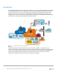
Campus VoIP Server Internet Logical Topology of a Campus Network The goal of this paper is to show exactly how to configure Dell N-Series and Cisco Catalyst switches to directly attach and work together in a heterogeneous network. While the examples presented in this document use Dell N3024 switches, the same commands can be used to configure any of the N-Series switches listed below.
1 Overview Connecting a Dell Networking N-Series switch to a Cisco Catalyst switch is a straightforward process; minimal effort is required to integrate the N-Series switch into an existing network. This guide is designed as a supplement to the N-Series User’s Guide, to help users successfully interconnect N-Series switches into a Campus Network. It provides easy-to-use steps to configure Dell Networking N-Series switches to work seamlessly with Cisco Catalyst switches.
2 Deployment Scenarios In the sections that follow, a variety of network deployment scenarios are discussed along with step-by-step instructions and commands required to build each setup. 2.1 Virtual LANs A Virtual Local Area Network (VLAN) is an implementation of IEEE specification 802.1Q. Operating at layer 2 of the OSI reference model, a VLAN is a means of parsing a single network into logical groups of users or organizations as if they physically resided on their own dedicated LAN segment.
2.1.1 Configuring VLANS — Dell N-Series To configure a VLAN on the Dell N-Series, the command vlan 30 is issued in configuration mode and the name “Management” is assigned to the VLAN. Configuration mode is then exited and the show vlan command is issued to verify creation of the VLAN.
C6504(config)#vlan 30 C6504(config-vlan)#name Management % Applying VLAN changes may take few minutes. Please wait... C6504(config-vlan)#end C6504#show vlan brief VLAN Name Status Ports ---- --------------------------- --------- -----------------------30 Management active Adding ports to the VLAN Creating a VLAN with the preceding commands only creates the framework of the VLAN. Not until one or more ports are assigned to the VLAN does it effectively serve the purpose of a virtual LAN.
2.2 Multiple Virtual LANs Configuring multiple VLANs on a switch to allow several broadcast domains within the switch or with other switches is typically desired. Figure 5 shows how multiple ports from each switch can be assigned to the same VLAN, allowing end devices attached to these ports to only communicate with each other via layer 2 switching.
N3024(config-vlan31-35)#vlan 31 N3024(config-vlan31)#name Public N3024(config-vlan31)#vlan 33 N3024(config-vlan32)#name Guest N3024(config-vlan32)#end N3024#show vlan VLAN ----30 31 32 33 34 35 Name --------------Management Public VLAN0032 Guest VLAN0034 VLAN0035 Ports ------------Gi1/0/1 Type -------------Static Static Static Static Static Static Adding ports to a VLAN Once the VLANs are created, use the following commands to assign ports to each VLAN.
2.2.2 Configuring Multiple VLANS — Cisco Catalyst The following commands illustrate how to create multiple VLANs on the Cisco Catalyst. First, the switch is put in configuration mode, then the vlan 30-35 command is issued to create VLANs 30 through 35. Optionally, names can be given to each VLAN to help identify them. Configuration mode is then exited and the show vlan brief command is issued to verify the creation of the VLANs. C6504#configure terminal Enter configuration commands, one per line.
C6504(config-if-range)#end C6504#show vlan brief VLAN ---1 30 31 32 33 34 35 Name -------------------------------default Management Public VLAN0032 Guest VLAN0034 VLAN0035 Status --------active active active active active active active Ports ----------------------------Gi4/1, Gi4/2 Gi4/3, Gi4/4, Gi4/5, Gi4/6 Gi4/7, Gi4/8, Gi4/9, Gi4/10 Repeat the commands above to assign ports to each VLAN. 2.
part of the command for assigning ports to the LAG. In the configurations in this section, for example, channel-group 5 refers to port-channel 5 as well as LAG 5. Figure 6 and the example commands below show both switches using LAG 5.
First, interface port channel 5 is configured and a description is added. The port is activated as a switchport and switchport trunking encapsulation dot1Q is enabled. The port channel is then removed from an administrative shutdown state. The interface range 2/1 and 2/2 are enabled as switchports. Next, the ports are added to port channel 5 and LACP negotiation is enabled unconditionally by using active. The ports are then removed from an administrative shutdown state.
Before connecting switches in a loop, it is highly recommended that spanning tree be enabled on all switches. This guide provides examples and commands for configuring spanning tree on the N-Series switches when connecting to a Cisco Catalyst. Refer to the spanning tree sections of this document or consult the User’s Guide for each switch for more information on configuring spanning tree. 5 13 Cisco 6504 13 5 Dell N3024-1 8 Dell N3024-2 8 Multiple Link Aggregation Groups 2.4.
2 3 4 5 6 7 - Destination MAC, VLAN, EtherType, source module and port Id Source IP and source TCP/UDP port Destination IP and destination TCP/UDP port Source/Destination MAC, VLAN, EtherType, source MODID/port Source/Destination IP and source/destination TCP/UDP port Enhanced hashing mode All configured port channels on the switch can be seen by using the show interfaces port-channel command. Note: Enhanced hashing mode offers excellent load balancing performance.
U f M m u d - in use N - not in use, no aggregation failed to allocate aggregator not in use, no aggregation due to minimum links not met not in use, port not aggregated due to minimum links not met unsuitable for bundling default port w - waiting to be aggregated Number of channel-groups in use: 1 Number of aggregators: 1 Group Port-channel Protocol Ports ------+-------------+-----------+-------------------------------------------13 Po13(SU) LACP Te2/3(P) Te2/4(P) Last applied Hash Distribution Algorith
Key Active Standby 5 13 Cisco 6504 13 5 Dell N3024-1 Dell N3024-2 8 8 LACP Standby 2.5.1 Configuring LACP Standby — Dell N-Series There is no specific configuration required for Dell N-Series switches. For hot-standby LACP links to work, one switch in the LAG needs to support the max-bundle interface command. The Dell switches must be configured to participate in the LAG and LACP must be enabled. To ensure LACP is enabled on each participating Ethernet port the command show lacp can be used.
port oper priority: port Oper timeout: LACP Activity: Aggregation: synchronization: collecting: distributing: expired: port Te1/0/2 LACP Statistics: LACP PDUs send: LACP PDUs received: 21 32768 SHORT ACTIVE AGGREGATABLE FALSE FALSE FALSE FALSE 60286 2290 Dell Campus Networking Interoperability with Cisco Catalyst 1.1 | version 1.
2.5.2 Configuring LACP Standby — Cisco Catalyst This section covers the configuration required on the Cisco 6504-E switch to enable LACP port standby. The command lacp max-bundle 1 is issued to both LAGs to reduce participating ports from two to one. The second Ethernet port participating in each of the two port channels have their LACP port-priority set to the maximum of 65535 to ensure that these physical ports will be in standby.
In this example, if a cable or port failure were to occur on ports te2/1 and te2/2 on the Cisco 6504, the show command would display the following: C6504#show etherchannel summary Flags: D - down P - bundled in port-channel I - stand-alone s – suspended H - Hot-standby (LACP only) R - Layer3 S - Layer2 U - in use N - not in use, no aggregation f - failed to allocate aggregator M - not in use, no aggregation due to minimum links not met m - not in use, port not aggregated due to minimum links not met u - uns
2.6 Spanning Tree Protocol (RSTP-PV and RPVST+) In traditional STP and Rapid STP (802.1d and 802.1w respectively), layer 2 loops are prevented by placing certain ports in blocking (STP) or discarding (RSTP) states. The overall effect of this is half of the available Ethernet links leading back to the core of a network are not in use most of the time. By using a STP instance per VLAN, a manual load balancing method can be achieved allowing overall better utilization of available bandwidth in a network.
spanning-tree vlan n-n is used to show that the VLANs specified have the STP root bridge running on that respective switch. Note: Configuration for both switches is identical except for the VLAN range. The variable n is inserted in the configuration below to represent the VLAN ID. The first switch is configured for VLAN 30-32 and the second switch used VLAN 33-35.
Hello Time 2 Sec Max Age 20 sec Forward Delay 15 sec Aging Time 300 sec Interface Role Sts Cost Prio.Nbr --------- ---------- ------------- --------- -------Po5 Designated Forwarding 2000 128.654 Po8 Designated Forwarding 1000 128.657 N3024-1#show spanning-tree vlan 33 VLAN 33 Spanning-tree enabled protocol rpvst RootID Priority 4129 Address 001E.C9DE.
N3024-2#show spanning-tree vlan 33 VLAN 33 Spanning Tree: Enabled Mode: rapid-pvst RootID Priority 33 Address 001E.C9E5.BC53 Cost 0 Port This switch is the root Hello Time: 2s Max Age: 20s Forward Delay: 15s BridgeID Priority 33 (priority 0 sys-id-ext 33) Address 001E.C9E5.BC53 Hello Time: 2s Max Age: 20s Forward Delay: 15s Aging Time 300 sec Interface --------Po8 Po13 Role ---------Designated Designated Sts ------------Forwarding Forwarding Cost --------1000 2000 Prio.Nbr -------128.217 128.
C6504#configure terminal Enter configuration commands, one per line. End with CNTL/Z. C6504(config)#spanning-tree mode rapid-pvst C6504(config)#end C6504#show spanning-tree vlan 30-35 summary Switch is in rapid-pvst mode Root bridge for VLAN0030 is 8222.001e.c9de.d11a. Root bridge for VLAN0031 is 8223.001e.c9de.d11a. Root bridge for VLAN0032 is 8224.001e.c9de.d11a. Root bridge for VLAN0033 is 8225.001e.c9de.d142. Root bridge for VLAN0034 is 8226.001e.c9de.d142. Root bridge for VLAN0035 is 8227.001e.c9de.
2.7 Multiple Spanning Tree Protocol Multiple Spanning Tree Protocol (MSTP, 802.1Q-2005) defines an extension to RSTP by allowing VLANs to be grouped together in MST instances. This reduces the number of STP instances found with PVSTP+ deployments, increasing available compute resources on switches participating in STP. Figure 10 shows how the previous RPVSTP+ topology can be simplified into two MST instances.
2.7.1 Configuring MST — Dell N-Series The configuration below is for both Dell switches, N3024-1 and N3024-2. The mst instance priority value on each mst instance for each switch determines STP root priority, where the lower the value the higher the priority for selection. This setting ensures that the respective switch becomes the root for that MST instance. The default priority is 32768.
Path Cost Root Port 0 Bridge ID Priority 4096 Address 001E.C9DE.D11A Hello Time 2 Sec Max Age 20 sec Forward Delay 15 Name State Prio.Nbr Cost Sts Role RestrictedPort --------- -------- --------- --------- ---- ----- -------------Po5 Enabled 96.654 2000 FWD Desg No Po8 Enabled 96.
Address Path Cost Root Port 001E.C9DE.D11A 1000 Po8 Bridge ID Priority 16384 Address 001E.C9DE.D142 Hello Time 2 Sec Max Age 20 sec Forward Delay 15 Name --------Po8 Po13 State -------Enabled Enabled Prio.Nbr --------96.657 96.
2.7.2 Configuring MST — Cisco Catalyst In the following example, MST 0 is set to a priority of 4096. This insures that this switch will be the STP root for instance 0. MST instance 0 is actually an Internal Spanning Tree (IST) and is limited to one per region. Treat IST as a management STP instance and all non-assigned VLANs are placed in this instance by default. The show spanning-tree mst 1, 2 command is then ran to show VLAN assignments and port participation in the STP structure.
2.8 Cisco Unidirectional Link Detection Interoperability The Unidirectional Link Detection (UDLD) feature detects unidirectional links on physical ports. A unidirectional link is a forwarding anomaly in a Layer 2 communication channel in which a bi-directional link stops passing traffic in one direction. UDLD must be enabled on the both sides of the link in order to detect a unidirectional link. The UDLD protocol operates by exchanging packets containing information about neighboring devices.
Time out interval: 5 Entry 1 --Expiration time: 37 Cache Device index: 1 Current neighbor state: Bidirectional Device ID: 13705M1334LF Port ID: Te1/0/1 Neighbor echo 1 device: 68EFBDEAB180 Neighbor echo 1 port: Te2/1 Message interval: 15 Time out interval: 5 CDP Device name: N3024 35 Dell Campus Networking Interoperability with Cisco Catalyst 1.1 | version 1.
2.9 Interoperability with Cisco Discovery Protocol Dell Networking N-Series switches participate in the Industry Standard Discovery Protocol (ISDP) and are able to both discover and be discovered by devices that support the Cisco Discovery Protocol (CDP). ISDP is a proprietary Layer 2 network protocol that inter-operates with Cisco network equipment and is used to share information between neighboring devices.
2.9.2 Interoperability with Cisco Discovery Protocol — Cisco Catalyst The following commands are similar to the Dell N-Series switches with CDP substituted for ISDP. The following shows CDP is enabled, the neighbors detected and how to verify and enable an interface where CDP has been disabled.
2.10 Filtering Cisco Proprietary Protocols Network Administrators often run into problems receiving multiple Cisco proprietary protocols on standards based switches, which causes unexpected results on the network. Therefore, Dell Networking has developed an easy way to block Cisco protocols when necessary. By applying built-in Access Control Lists (ACL) that block individual Cisco protocols on each port, the user can filter out unwanted packets from their network.
2.11 Management VLAN vs Switch Virtual Interface Management traffic is the basic messaging required to keep the network up and running. It uses BPDUs, VTP packets, CDPs and keep alives, in addition to management access traffic such as HTML, CLI, and SNMP. A Management VLAN is a VLAN specifically created for the use of managing the switch. On a Dell Networking N3000, VLAN 1 is known as the default VLAN because all ports on the switch are assigned to it by default.
defined. To create a Management VLAN or SVI, create a VLAN interface and then add an IP address to this interface. 2.11.1 Configuring Management VLAN — Dell N-Series The example below shows the commands for setting up a management VLAN on the Dell Networking N3000. After creating a username and password for remote access to the switch, create a VLAN and assign it an IP address. Assign trunk ports to be attached to the Cisco Catalyst or other switch.
2.11.2 Configuring Management VLAN — Cisco Catalyst Run the commands below on the Cisco Catalyst switch to create an SVI, which allows in-band management to the switch. C6504#configure terminal Enter configuration commands, one per line. End with CNTL/Z. C6504(config)#vlan 30 C6504(config-vlan)#name "In-Band Management" C6504(config-vlan)#exit % Applying VLAN changes may take few minutes. Please wait... C6504(config)#interface vlan 30 C6504(config-if)#ip address 192.168.30.51 255.255.255.
A Additional Resources Support.dell.com is focused on meeting your needs with proven services and support. DellTechCenter.com is an IT Community where you can connect with Dell EMC customers and Dell EMC employees to share knowledge, best practices and information about Dell EMC products and installations. Referenced or recommended Dell EMC publications: B Dell Networking Support http://www.dell.com/support Dell TechCenter (community forums and blogs for Dell EMC customers) http://delltechcenter.
Support and Feedback Contacting Technical Support Support Contact Information Web: http://support.dell.com/ Telephone: USA: 1-800-945-3355 Feedback for this document We encourage readers of this publication to provide feedback on the quality and usefulness of this document by sending an email to Dell_Networking_Solutions@Dell.