Dell Networking N1500 Series Switch Getting Started Guide 使用入门指南 入門指南 Panduan Pengaktifan はじめに 시작 안내서
Dell Networking N1500 Series Switch Getting Started Guide Regulatory Models: N1524, N1524P, N1548, N1548P
Notes, Cautions, and Warnings NOTE: A NOTE indicates important information that helps you make better use of your switch. CAUTION: A CAUTION indicates either potential damage to hardware or loss of data and tells you how to avoid the problem. WARNING: A WARNING indicates a potential for property damage, personal injury, or death. ____________________ Copyright © 2015 Dell Inc. All rights reserved. This product is protected by U.S. and international copyright and intellectual property laws.
Contents 1 Introduction . 2 Dell Networking N1500 Series Overview 3 Hardware Overview . . . . . . . . . . . . . . . . . . . . . . . . 7 . . . 7 . . . . . . . . . . . . . . . . . 8 Dell Networking N1500 Series Front Panel . . . . . . . . 8 Switch Ports . . . . . . . . . . . . . . . . . . . . 10 Console Port . . . . . . . . . . . . . . . . . . . . 11 . . . . . . . . . . . . . . . . . . . . . . 11 USB Port Reset Button . . . . . . . . . . . . . . . . . . . . Port and System LEDs . .
4 Dell Networking N1500 Series Installation . . . . . . . . . . . . . . . Site Preparation . . . . . . . . 15 . . . . . . . . . . . . . . . . . . . . . 15 . . . . . . . . . . 16 . . . . . . . . . . . . . . . . . 16 . . . . . . . . . . . . . . . . . . 16 Unpacking the N1500 Series Switch Package Contents. Unpacking Steps . . . . . . . . 17 . . . . . . . . . . . . . . . . . 17 Rack Mounting the N1500 Series Switch Installing in a Rack Installing as a Free-standing Switch 5 . . . . . . . .
Introduction This document provides basic information about the Dell Networking N1500 Series switches, including how to install a switch and perform the initial configuration. For information about how to configure and monitor switch features, see the User’s Configuration Guide, which is available on the Dell Support website at dell.com/support for the latest updates on documentation and firmware.
Hardware Overview This section contains information about device characteristics and modular hardware configurations for the Dell Networking N1500 Series switches. All Dell Networking N1500 non-PoE models are 1U, rack-mountable switches with the following physical dimensions: • 440.0 x 257.0 x 43.5 mm (W x D x H). • 17.3 x 10.1 x 1.7 inches (W x D x H). All Dell Networking N1500 PoE models are 1U, rack-mountable switches with the following physical dimensions: • 440.0 x 387.0 x 43.5 mm (W x D x H).
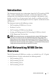
Figure 1-2. Dell Networking N1524 Close-up The Dell Networking N1500 Series switch front panel, shown in Figure 1-2, has status LEDs for over-temperature alarm, internal power, and system health status on the top row. The bottom row of status LEDs displays the stack master, redundant power supply (RPS 720) status and fan alarm status. Figure 1-3.
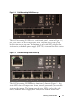
Switch Ports The Dell Networking N1524/N1524P front panel provides 24 Gigabit Ethernet (10BASE-T, 100BASE-TX, 1000BASE-T) RJ-45 ports that support auto-negotiation for speed, flow control, and duplex. The Dell Networking N1500 Series models support four SFP+ 10G ports. Dell-qualified SFP+ transceivers are sold separately. The Dell Networking N1548/N1548P front panel provides 48 Gigabit Ethernet (10BASE-T, 100BASE-TX, 1000BASE-T) RJ-45 ports that support auto-negotiation for speed, flow control, and duplex.
Console Port The Dell Networking console port is located on the right side of the front panel and is labeled with a symbol. The console port provides serial communication capabilities, which allows communication using RS-232 protocol. The serial port provides a direct connection to the switch and allows access to the CLI from a console terminal connected to the port through the provided serial cable (with RJ45 YOST to female DB-9 connectors).
Port and System LEDs The front panel contains light emitting diodes (LEDs) that indicate the status of port links, power supplies, fans, stacking, and the overall system status. For further information about the status that the LEDs indicate, see the User’s Configuration Guide. Stack Master LED and Stack Number Display The Dell Networking Stack Master LED is located on the right side of the front panel and is labeled with a symbol.
Dell Networking N1500 Series Back Panel The following images show the back panels of the Dell Networking N1500 and N1500P Series switches. Figure 1-4. N1500 Series Back Panel Fan Vents AC Power Receptacle Figure 1-5. N1524P/N1548P Back Panel Power Supplies CAUTION: Remove the power cable from the power supplies prior to removing the power supply module itself. Power must not be connected prior to insertion in the chassis.
Ventilation System Two fixed internal fans cool the N1500 Series switches. Dell Networking N1500 Series Model Summary Table 1-2.
Dell Networking N1500 Series Installation Site Preparation N1500 Series switches can be mounted in a standard 48.26 cm (19-inch) rack or placed on a flat surface. Make sure that the chosen installation location meets the following site requirements: • Power — The switch is installed near an easily accessible 100–240 VAC, 50–60 Hz outlet. • Clearance — There is adequate front and rear clearance for operator access. Allow clearance for cabling, power connections, and ventilation.
Unpacking the N1500 Series Switch Package Contents When unpacking each switch, make sure that the following items are included: • One Dell Networking switch • One RJ-45 to DB-9 female cable • One rack-mount kit: two mounting brackets, bolts, and cage nuts • One set of self-adhesive rubber pads for a free-standing configuration (four pads are included) Unpacking Steps NOTE: Before unpacking the switch, inspect the container and immediately report any evidence of damage.
Rack Mounting the N1500 Series Switch WARNING: Read the safety information in the Safety and Regulatory Information as well as the safety information for other switches that connect to or support the switch. The AC power connector is on the back panel of the switch. Installing in a Rack WARNING: Do not use rack mounting kits to suspend the switch from under a table or desk, or attach it to a wall. CAUTION: Disconnect all cables from the switch before continuing.
4 Insert the switch into the 48.26 cm (19 inch) rack, ensuring that the rackmounting holes on the switch line up to the mounting holes in the rack. 5 Secure the switch to the rack with either the rack bolts or cage nuts and cage-nut bolts with washers (depending on the kind of rack you have). Fasten the bolts on bottom before fastening the bolts on top. CAUTION: Make sure that the supplied rack bolts fit the pre-threaded holes in the rack. NOTE: Make sure that the ventilation holes are not obstructed.
Stacking Multiple Switches It is possible to stack upto four N1500 Series switches using the SFP+ ports. NOTE: N1500 Series switches support stacking only with other N15xx series switches. Do not stack N1500 Series switches with N2000, N3000, or N4000 series switches. When multiple switches are connected using the stack ports, they operate as a single unit with up to 192 RJ-45 front panel ports. The stack operates and is managed as a single entity.
Figure 1-7. Unit 1 Unit 2 Unit 3 The stack in Figure 1-7 is connected in a ring topology and has the following physical connections between the switches: 20 • The left SFP+ port Te1/0/1 on Unit 1 (top) is connected to the right SFP+ port Te2/0/2 on Unit 2. • The left SFP+ port Te2/0/1 on Unit 2 (middle) is connected to the right SFP+ port Te3/0/2 on Unit 3. • The left SFP+ port Te3/0/1 on Unit 3 (bottom) is connected to the right SFP+ port Te1/0/2 on Unit 1.
Stacking Standby The stacking feature supports a Standby or backup unit that assumes the Master unit role if the Master unit in the stack fails. As soon as a Master failure is detected in the stack, the Standby unit enables the control plane on the new Master unit and synchronizes all other stack units with the current configuration. The Standby unit maintains a synchronized copy of the running configuration for the stack.
Starting and Configuring the Dell Networking N1500 Series Switch The following flow chart provides an overview of the steps you use to perform the initial configuration after the switch is unpacked and mounted. Figure 1-8.
Connecting a N1500 Series Switch to a Terminal After completing all external connections, connect a serial terminal to a switch to configure the switch. NOTE: Read the Release Notes for this product before proceeding. You can download the Release Notes from the Dell Support website at dell.com/support. NOTE: We recommend that you obtain the most recent version of the user documentation from the Dell Support website at dell.com/support.
3 Connect the RJ-45 connector on the cable directly to the switch console port. The Dell Networking console port is located on the right side of the front panel and is labeled with a |O|O| symbol, as shown in Figure 1-9 on page 24. NOTE: Serial console access to the stack manager is available from any serial port via the local CLI. Only one serial console session at a time is supported. Figure 1-9.
Connecting a Switch to a Power Source CAUTION: Read the safety information in the Safety and Regulatory Information manual as well as the safety information for other switches that connect to or support the switch. All N1500 Series switch models have one internal power supply. The power receptacles are on the back panel. AC and DC Power Connection 1 Make sure that the switch console port is connected to a VT100 terminal or VT100 terminal emulator via the RJ-45 to DB-9 female cable. 2 Using a 5-foot (1.
Figure 1-10. AC and DC Power Connection to an N1548 Switch To DC Power Source (Optional) To AC Power Source Booting the Switch When the power is turned on with the local terminal already connected, the switch goes through a power-on self-test (POST). POST runs every time the switch is initialized and checks hardware components to determine if the switch is operational before completely booting. If POST detects a critical problem, the program flow stops.
Performing the Initial Configuration The initial configuration procedure is based on the following assumptions: • The Dell Networking switch does not have a saved configuration. • The Dell Networking switch booted successfully. • The console connection is established, and the Dell Easy Setup Wizard prompt appears on the screen of a VT100 terminal or terminal equivalent. The initial switch configuration is performed through the console port.
Initial Configuration Procedure Perform the initial configuration by using the Dell Easy Setup Wizard or by using the CLI. The wizard automatically starts when the switch configuration file is empty. It is possible to exit the wizard at any point by entering [ctrl+z], but all configuration settings specified will be discarded, and the switch will use the default values.
Example Session This section describes a Dell Easy Setup Wizard session. The following values are used by the example session: • The SNMP community string to be used is public. • The network management system (NMS) IP address is 10.1.2.100. • The user name is admin, and the password is admin123. • The IP address for the VLAN 1 routing interface is 10.1.1.200 with a subnet mask of 255.255.255.0. • The default gateway is 10.1.1.1 The setup wizard configures the initial values as defined above.
Dell Easy Setup Wizard Console Example The following example contains the sequence of prompts and responses associated with running an example Dell Easy Setup Wizard session, using the input values listed above. After the switch completes the POST and is booted, the following dialog appears: Unit 1 - Waiting to select management unit)> Applying Global configuration, please wait...
automatically assigns the highest access level [Privilege Level 15] to this account. You can use Dell Network Manager or other management interfaces to change this setting, and to add additional management system information later. For more information on adding management systems, see the user documentation. To add a management station: Please enter the SNMP community string to be used.
To access the switch through any Management Interface you can . Set up the IP address for the Management Interface. . Set up the default gateway if IP address is manually configured on the routing interface. Step 4: Would you like to set up the VLAN1 routing interface now? [Y/N] y Please enter the IP address of the device (A.B.C.D) or enter “DHCP” (without the quotes) to automatically request an IP address from the network DHCP server: 10.1.1.200 Please enter the IP subnet mask (A.B.C.D or /nn): 255.255.
Next Steps After completing the initial configuration described in this section, connect any of the front-panel switch ports to your production network for in-band remote management. If DHCP was configured for the VLAN 1 management interface IP address, the interface will acquire its IP address from a DHCP server on the network. To discover the dynamically-assigned IP address, use the console port connection to issue the following command: • For the VLAN 1 routing interface, enter show ip interface vlan 1.
NOM Information (Mexico Only) The following information is provided on the device(s) described in this document in compliance with the requirements of the official Mexican standards (NOM): Table 1-3. NOM Information Required Information Details Exporter: Dell Inc. One Dell Way Round Rock, TX 78682 Importer: Dell Computer de México, S.A. de C.V. Paseo de la Reforma 2620 - 11o Piso Col. Lomas Altas 11950 México, D.F. Ship to: Dell Computer de México, S.A. de C.V.
Table 1-3. NOM Information (continued) Required Information Details N1548P: • 110V circuit: ~5.23A • 220V circuit: ~2.76A NOTE: The current values shown here are for single power supply consumption.
Dell Networking N1500 系列交换机 使用入门指南 管制型号:N1524、 N1524P、 N1548、 N1548P
注、小心和警告 注:“ 注 ” 表示帮助您更好地使用该交换机的重要信息。 小心:“ 小心 ” 表示可能会损坏硬件或导致数据丢失,并说明如何避免此类 问题。 警告:“ 警告 ” 表示可能会导致财产损失、人身伤害甚至死亡。 ____________________ 版权所有 © 2014 Dell Inc. 保留所有权利。本产品受美国版权 、国际版权和知识产权法律保护。 Dell™ 和 Dell 徽标是 Dell Inc. 在美国和 / 或其他司法管辖区的商标。本文档中所述及的其他 商标和产品名称可能是其各自所属公司的商标。 2015-05 P/N M25TN Rev.
目录 1 简介 . . . . . . . . . . . . . . . . . . . . . . . . . . . . 2 Dell Networking N1500 系列概述 . 3 硬件概述 . . . 40 . . . . . . . . . . . . . . . . . . . . . . . . 41 Dell Networking 前面板 N1500 系列 . . . . . . . . 41 交换机端口 . . . . . . . . . . . . . . . . . . . . . 43 控制台端口 . . . . . . . . . . . . . . . . . . . . . 44 . . . . . . . . . . . . . . . . . . . . . 44 . . . . . . . . . . . . . . . . . . . . . . 44 USB 端口 . 重设按钮 端口和系统 LED . . . . . . . . . . . . . . . . . . 堆栈主装置 LED 和堆栈编号显示屏 45 .
机架安装 N1500 系列交换机 在机架中安装 . . . . . . . . . . . . . 50 . . . . . . . . . . . . . . . . . . . 50 . . . . . . . . . . . . . . . 51 . . . . . . . . . . . . . . . . . . . . 52 安装为独立式交换机 堆叠多台交换机 . 创建交换机堆栈 . . . . . . . . . . . . . . . . . . 5 启动和配置 Dell Networking N1500 系列交换机 . . . . . . . . . . . . . . . . . . . . . 将 N1500 系列交换机连接至终端 将交换机连接到电源 . 54 . . . . . . . . . . 55 . . . . . . . . . . . . . . . . . 57 . . . . . . . . . . . . . . . 57 . . . . . . . . . . . . . . . . . . . . . . .
简介 本说明文件提供有关 Dell Networking N1500 系列交换机的基本信息,包括 如何安装交换机和执行初始配置。有关如何配置和监测交换机功能的信 息,请参阅 Dell 支持网站上的 《User's Configuration Guide》(用户配置 指南)。要获取有关说明文件及固件的最新更新,请访问该站点,网址为 dell.
硬件概述 本节包含有关 Dell Networking N1500 系列交换机设备特性和模块化硬件 配置的信息。 所有 Dell Networking N1500 非 PoE 型号为 1U 机架安装式交换机,物理尺 寸如下: • 440.0 x 257.0 x 43.5 毫米 (宽 x 深 x 高)。 • 17.3 x 10.1 x 1.7 英寸 (宽 x 深 x 高)。 所有 Dell Networking N1500 PoE 型号为 1U 机架安装式交换机,物理尺寸 如下: • 440.0 x 387.0 x 43.5 毫米 (宽 x 深 x 高)。 • 17.3 x 15.2 x 1.7 英寸 (宽 x 深 x 高)。 Dell Networking 前面板 N1500 系列 下图显示 Dell Networking N1500 系列 中四个交换机型号的前面板。 图 1-1.
图 1-2. Dell Networking N1524 特写 Dell Networking N1500 系列 交换机前面板 (如图 1-2 所示)的状态 LED 指 示灯顶行显示温度过高警报、内部电源和系统运行状况。状态 LED 指示灯 的底行显示堆栈主装置、冗余电源 (RPS 720) 状态和风扇警报状态。 图 1-3.
交换机端口 Dell Networking N1524/N1524P 前面板提供 24 个千兆位以太网(10BASE-T、 100BASE-TX 和 1000BASE-T) RJ-45 端口,这些端口支持针对速度、双工 模式和流量控制进行自动协商。Dell Networking N1500 系列 型号支持四个 SFP+ 10G 端口。经 Dell 认可的 SFP+ 收发器是单独销售的。 Dell Networking N1548/N1548P 前面板提供 48 个千兆位以太网(10BASE-T、 100BASE-TX 和 1000BASE-T) RJ-45 端口,这些端口支持针对速度、双工 模式和流量控制进行自动协商。 N1548 N1548P 型号支持四个 SFP+ 10G 端口。经 Dell 认可的 SFP+ 收发器是单独销售的。 前面板交换机端口具有以下特征: • 交换机将自动检测 RJ-45 端口上的交叉和直通电缆之间的差异,并自动 选择 MDI 或 MDIX 配置以与另一端匹配。 • 对于使用 10BASE-T、100BASE-TX 和 1000BASE-T 技术的标准 5 类 UTP 电缆,
控制台端口 Dell Networking 控制台端口位于前面板的右侧,标有 符号。控制台 端口提供串行通信功能,允许使用 RS-232 协议的通信。串行端口提供与交 换机的直接连接,并允许从通过提供的串行电缆 (带 RJ-45 YOST 连接阴 型 DB-9 插座)连接至端口的控制台终端访问 CLI。 控制台端口可单独配置,并可作为 1200 波特到 115,200 波特的异步链接 运行。 Dell CLI 只支持更改速度。默认值为 9600 波特率、8 个数据位、无奇偶校 验、 1 个停止位、无流量控制。 USB 端口 Dell Networking USB 端口位于前面板右侧,标有 符号。 A 型阴型 USB 端口支持兼容 USB 2.
端口和系统 LED 前面板上有发光二极管 (LED),这些发光二极管指示端口链路的状态、电 源设备、风扇、堆栈和总体系统状态。 有关 LED 指示的状态的详细信息,请参阅用户配置指南。 堆栈主装置 LED 和堆栈编号显示屏 Dell Networking 堆栈主装置 LED 位于前面板右侧,标有 主装置 LED 指示交换机是否作为主装置或堆栈成员运行。 符号。堆栈 表 1-1.
Dell Networking N1500 系列背面板 下图显示了 Dell Networking N1500 和 N1500P 系列交换机的背面板。 图 1-4. N1500 系列 背面板 风扇通风孔 交流电源插座 图 1-5.
Dell Networking N1500 系列型号摘要 表 1-2.
Dell Networking N1500 系列安装 站点准备 N1500 系列 交换机可以安装在标准的 48.26 厘米(19 英寸)机架中或放置 在平坦的表面上。 确保选择满足以下站点要求的安装位置: • 电源 — 交换机靠近易于插拔的 100–240 VAC, 50–60 Hz 电源插座 安装。 • 空间 — 前后留有足够的空间以便于操作员进出。请留出用于布线、电 源连接和通风的空间。 • 布线 — 布线应远离电气干扰源 (例如无线电发送器、广播放大器、电 线和荧光照明装置)。 • 环境温度 - 交换机操作环境温度的范围是 0 至 45°C(32 至 113°F),最 大相对湿度为 95%,非冷凝。 注:在 900 米 (2955 英尺)以上,每升高 300 米 (985 英尺)最高温度下 降 1°C (1.
打开 N1500 系列交换机包装 套件内容 在打开每个交换机的包装时,确保均包含下列物品: • 一台 Dell Networking 交换机 • 一根 RJ-45 到 DB-9 的插孔电缆 • 一个机架安装套件:两个安装支架、螺栓和固定框架螺母、 • 一套自粘橡胶垫,用于独立式配置 (附带四个垫) 打开包装步骤 注:打开交换机包装之前,请先检查包装箱,如有损坏迹象请立即报告。 1 将包装箱放在清洁的平面上并剪断所有捆扎包装箱的带子。 2 打开包装箱或取下包装箱顶盖。 3 小心地从包装箱中取出交换机,并将其放置在稳固清洁的表面上。 4 取下所有包装材料。 5 检查产品和附件有无损坏。 使用入门指南 49
机架安装 N1500 系列交换机 警告:阅读安全和管制信息中的安全信息以及连接或支持该交换机的其他交 换机的安全信息。 交流电源连接器位于交换机背面板上。 在机架中安装 警告:请勿使用机架安装工具包在桌下悬挂交换机或将其挂在墙上。 小心:断开所有电缆与交换机的连接,然后才可继续操作。从交换机下方卸 下所有自粘垫 (如果已粘贴)。 小心:在将多台交换机安装到机架中时,请倒置安装交换机。 1 将随附的机架安装支架放置在交换机一侧,确保交换机上的安装孔对准 机架安装支架上的安装孔。图 1-6 显示支架的安装位置。 图 1-6. 安装支架 2 将附带的螺栓插入机架安装孔,然后用螺丝刀将其拧紧。 3 重复此过程,以安装交换机另一侧的机架安装支架。 4 将交换机插入 48.
安装为独立式交换机 注:我们强烈建议您将交换机安装在机架中。 如果未将交换机安装在机架中,请将其安装在平坦的表面上。表面必须能 够承受交换机与交换机电缆的重量。交换机附带的四个自粘橡胶垫。 1 在交换机底部标记的每个位置上贴上自粘橡胶垫。 2 将交换机放置在平面上,并通过两侧各留出 5 厘米 (2 英寸)、背面留 出 13 厘米 (5 英寸)的空间确保其能够正常通风。 使用入门指南 51
堆叠多台交换机 使用 SFP+ 端口可堆叠多达四台 N1500 系列 交换机。 注:N1500 系列 交换机仅支持与其他 N15xx 系列交换机堆叠。请勿将 N1500 系列交换机与 N2000、 N3000 或 N4000 系列交换机堆叠。 当通过堆栈端口连接多台交换机时,它们将作为单个单元运行,配备多达 192 个 RJ-45 前面板端口。此堆栈作为单一实体操作和管理。 注:如果要安装一个交换机堆栈,应先将该堆栈组装和接线,然后再通电并 进行配置。堆栈首次通电时,交换机会选出主交换机,可能会占用堆栈中的任 何位置。在主单元上,前面板上的主 LED 指示灯将亮起。 创建交换机堆栈 通过将 SFP+ 端口成对配置为堆栈来创建堆栈。必须对要堆叠的每台交换 机完成此步骤,才能使用交换机前面板上的 SFP+ 堆栈端口连接相邻的单 元。 注:堆叠端口必须成对配置。可使用 Te1/0/2 配置 Te1/0/1,或使用 Te1/0/4 配 置 Te1/0/3。不允许其他组合。 图 1-7 (第 53 页上)显示环形拓扑中连接的交换机,这是建议用于堆栈的 拓扑。 1 将 SR、LR 或 CR 收发器和电缆连接到顶部交换机
图 1-7.
启动和配置 Dell Networking N1500 系列交换机 下面的流程图概述将交换机拆包并安装后执行初始配置所用的步骤。 图 1-8.
将 N1500 系列交换机连接至终端 完成所有外部连接后,将某个串行终端连接到交换机,以配置交换机。 注:请 先 阅 读本 产 品 的 版 本 说 明,然 后 继 续。您可以从 Dell 支持网站 dell.com/support 下载版本说明。 注:我 们建 议 您 从 Dell 支持 网 站获 取 用 户说明文件的最新版本,网址: dell.
图 1-9.
将交换机连接到电源 小心:阅读安全和管制信息手册中的安全信息以及连接或支持该交换机的其 他交换机的安全信息。 所有 N1500 系列交换机型号均有一个内部电源设备。电源插座位于背面 板上。 交流和直流电源连接 1 确保通过 RJ-45 到 DB-9 阴型电缆将交换机控制台端口连接至 VT100 终 端或 VT100 终端仿真器。 2 使用 5 英尺 (1.
图 1-10.
执行初始配置 初始配置过程基于以下假定: • Dell Networking 交换机没有保存的配置。 • Dell Networking 交换机已成功引导。 • 已建立控制台连接,并且在 VT100 终端或终端等同设备的屏幕上显示 Dell Easy Setup Wizard 提示。 通过控制台端口执行交换机初始配置。在初始配置后,您可以从已连接的 控制台端口管理交换机,或通过在初始配置过程中定义的接口对交换机进 行远程管理。 注:交换机未使用默认的用户名、密码和 IP 地址进行配置。 在设置交换机的初始配置前,请从网络管理员处获取以下信息: • 要分配给管理接口的 IP 地址。 • 网络的 IP 子网掩码。 • 管理接口默认网关的 IP 地址。 此外,交换机可以配置为使用 DHCP 引导并将自动获得 IP 地址和子网掩 码。在允许通过 Telnet (Telnet 客户端)或 HTTP (Web 浏览器)连接远 程管理交换机时需要这些设置。 启用远程管理 在 Dell Networking N1500 系列交换机上,请使用交换机前面板上的任何端 口进行带内管理。默认情况下,所有交换
初始配置过程 通过使用 Dell Easy Setup Wizard 或 CLI 执行初始配置。在交换机配置文 件为空时,该向导会自动启动。通过输入 [ctrl+z] 可以随时退出向导,但 将放弃指定的所有配置设置,并且交换机将使用默认值。 注:如 果 60 秒 内 未 运 行 Dell Easy Setup Wizard 或未对初始 Easy Setup Wizard (简易设置向导)提示进行响应,交换机将进入 CLI 模式。使用空启 动配置重置交换机,以重新运行 Dell Easy Setup Wizard。 有关通过使用 CLI 执行初始配置的更多信息,请参阅 CLI 参考指南。本入门 指南介绍如何使用 Dell Easy Setup Wizard 进行交换机初始配置。此向导在 交换机上设置以下配置: 60 • 建立具有有效密码的初始特权用户帐户。该向导会在设置期间配置一个 有特权的用户帐户。 • 启用 CLI 登录和 HTTP 访问以只使用本地身份验证设置。 • 设置 VLAN 1 路由接口的 IP 地址,该接口的所有带内端口均为成员。 • 设置 SNMP 管理器在指定 IP 地址上
示例会话 本节介绍了一个 Dell Easy Setup Wizard 会话。示例会话使用以下值: • 要使用的 SNMP 团体字符串为 public。 • 网络管理系统 (NMS) 的 IP 地址为 10.1.2.100。 • 用户名为 admin,密码为 admin123。 • VLAN 1 路由接口的 IP 地址为 10.1.1.200,子网掩码为 255.255.255.0。 • 默认网关为 10.1.1.1 设置向导如上述定义配置初始值。完成向导后,交换机配置如下: • SNMPv2 已启用并且如上述定义设置团体字符串。默认情况下, SNMPv3 处于禁用状态。 • 如定义设置 admin 用户帐户。 • 网络管理系统已配置。在管理站中,您可以访问 SNMP、HTTP 和 CLI 接口。您也可以通过选择 (0.0.0.
Dell Easy Setup Wizard (Dell 简易设置向导)控制台示例 以下示例包含使用上述输入值时,与运行 Dell Easy Setup Wizard(Dell 简 易设置向导)会话示例关联的提示和响应顺序。 交换机完成 POST 和引导后,将显示以下对话框: Unit 1 - Waiting to select management unit)> Applying Global configuration, please wait... Welcome to Dell Easy Setup Wizard The Setup Wizard guides you through the initial switch configuration, and gets you up and running as quickly as possible. You can skip the setup wizard, and enter CLI mode to manually configure the switch.
Network Manager or other management interfaces to change this setting, and to add additional management system information later. For more information on adding management systems, see the user documentation. To add a management station: Please enter the SNMP community string to be used. [public]: public 注:如果已配置,默认访问级别将设置为用于访问 SNMP 管理接口的最高权 限级别。最初将仅激活 SNMPv2。将禁用 SNMPv3,直至返回而为 SNMPv3 配置安全访问 (例如引擎 ID,查看等)。 Please enter the IP address of the Management System (A.B.C.D) or wildcard (0.0.0.
To access the switch through any Management Interface you can . Set up the IP address for the Management Interface. . Set up the default gateway if IP address is manually configured on the routing interface. Step 4: Would you like to set up the VLAN1 routing interface now? [Y/N] y Please enter the IP address of the device (A.B.C.D) or enter “DHCP” (without the quotes) to automatically request an IP address from the network DHCP server: 10.1.1.200 Please enter the IP subnet mask (A.B.C.D or /nn): 255.255.
Applying Interface configuration, please wait...
NOM 信息 (仅限于墨西哥) 本说明文件中述及的符合墨西哥官方标准 (NOM) 要求的设备上均提供以 下信息: 表 1-3. NOM 信息 所需信息 详细信息 出口商: Dell Inc. One Dell Way Round Rock, TX 78682 进口商: Dell Computer de México, S.A.de C.V. Paseo de la Reforma 2620 - 11o Piso Col.Lomas Altas 11950 México, D.F. 收货地点: Dell Computer de México, S.A.de C.V. al Cuidado de Kuehne & Nagel de México S.de R.L. Avenida Soles No.55 Col.Peñon de los Baños 15520 México, D.F.
表 1-3. NOM 信息 (续) 所需信息 详细信息 N1548P: • 110V 电路:~5.23A • 220V 电路:~2.
Dell Networking N1500 系列交換器 入門指南 管制機型:N1524、N1524P、 N1548、N1548P
註,警示,警告 註:「註」表示可以幫助您更有效地使用交換器的重要資訊。 警示:「警示」表示可能導致硬體損壞或資料遺失,並告訴您如何避免發生 此類問題。 警告:「警告」表示有可能會導致財產損失、人身傷害甚至死亡。 ____________________ Copyright © 2015 Dell Inc. 版權所有,翻印必究。本產品受美國 與國際著作權與智慧財產權 法保護。Dell™ 與 Dell 徽標是 Dell Inc. 在美國和 / 或其他轄區的商標。本文提及的所有其他 標誌與名稱可能屬於其個別公司的商標。 2015-05 P/N M25TN Rev.
目錄 1 簡介 . . . . . . . . . . . . . . . . . . . . . . . . . . . . 2 Dell 網路設備 N1500 系列概觀 . 3 硬體概覽 . . . . . 72 . . . . . . . . . . . . . . . . . . . . . . . . 73 Dell 網路設備 N1500 系列前面板 . . . . . . . . . . 73 交換器連接埠 . . . . . . . . . . . . . . . . . . . 75 控制台連接埠 . . . . . . . . . . . . . . . . . . . 76 . . . . . . . . . . . . . . . . . . . . 76 . . . . . . . . . . . . . . . . . . . . . . 76 USB 連接埠 重設按鈕 連接埠和系統 LED . . . . . . . . . . . . . . . . 堆疊主裝置 LED 和堆疊號碼顯示 . 77 . . . . . . . . .
N1500 系列交換器機架安裝. 在機架中安裝 . . . . . . . . . . . . . 82 . . . . . . . . . . . . . . . . . . . 82 . . . . . . . . . . . . . . . 83 . . . . . . . . . . . . . . . . . . . . 84 安裝為獨立式交換器 堆疊多台交換器 . 建立交換器堆疊 . . . . . . . . . . . . . . . . . . 5 啟動和配置 Dell 網路設備 N1500 系列交換器 . . . . . . . . . . . . . . . . . . . 將 N1500 系列交換器連接至終端機 將交換器連接至電源 . 87 . . . . . . . . . 88 . . . . . . . . . . . . . . . . . 90 . . . . . . . . . . . . . . . . 90 . . . . . . . . . . . . . . . . . . . . . . .
簡介 本文件提供有關 Dell 網路設備 N1500 系列交換器的基本資訊,包括如何安裝 交換器及執行初始組態。如需瞭解如何設定及監控交換器功能 ,請參閱使用 者組態指南,該指南可從 Dell 支援網站 ( 網址是:dell.
硬體概覽 本節包含 裝置特色及 Dell 網路設備 N1500 系列交換器模組化硬體組態的相 關資訊。 所有 Dell 網路設備 N1500 非 PoE 機型都是 1U、機架可掛載交換器,且具有 下列實體尺寸 : • 440.0 x 257.0 x 43.5 公釐 ( 寬 x 深 x 高 )。 • 17.3 x 10.1 x 1.7 吋 ( 寬 x 深 x 高 )。 所有 Dell 網路設備 N1500 PoE 機型都是 1U、機架可掛載交換器,且具有下 列實體尺寸 : • 440.0 x 387.0 x 43.5 公釐 ( 寬 x 深 x 高 )。 • 17.3 x 15.2 x 1.7 吋 ( 寬 x 深 x 高 )。 Dell 網路設備 N1500 系列前面板 下列影像顯示了 Dell 網路設備 N1500 系列 四個交換器機型的前面板。 圖 1-1.
圖 1-2. Dell 網路設備 N1524 特寫 Dell 網路設備 N1500 系列 交換器前面板 ( 如 圖 1-2 所示 ) 具有狀態 LED 燈 以呈現過溫警報、內部電源,以及系統健全狀態 ( 位於最上面一列 )。狀態 LED 的最後一列顯示堆疊主裝置、備援電源供應器 (RPS720) 狀態和風扇警 報狀態。 圖 1-3.
交換器連接埠 Dell 網路設備 N1524/N1524P 前面板提供 24 Gigabit 乙太網路 (10BASE-T、 100BASE-TX、1000BASE-T) RJ-45 連接埠,其支援有關速度、流量控制和雙 工的自動交涉。Dell 網路設備 N1500 系列 機型支援 4 個 SFP+ 10G 連接埠。 Dell- 合格 SFP+ 收發器需要另外購買。 Dell 網路設備 N1548/N1548P 前面板提供 48 Gigabit 乙太網路 (10BASE-T、 100BASE-TX、1000BASE-T) RJ-45 連接埠,其支援有關速度、流量控制和雙 工的自動交涉。N1548/N1548P 支援 4 個 SFP+ 10G 連接埠。Dell- 合格 SFP+ 收發器需要另外購買。 前面板的交換器連接埠有下列特性 : • 交換器會自動偵測 RJ-45 連接埠交叉纜線和直通纜線之間的差異,並自 動選擇 MDI 或 MDIX 組態以符合另一端。 • RJ-45 連接埠使用 10BASE-T、100BASE-TX 和 1000BASE-T 技術,在標 準類別 5 UTP 纜線上支援完整 - 雙
控制台連接埠 Dell 網路設備 主控台連接埠位於前面板的右側 ,並標有 符號。主控 台連接埠提供序列通訊功能 ,而其允許使用 RS-232 通訊協定進行通訊。序 列連接埠有助於直接連線至交換器,並允許透過提供的序列纜線 ( 含連接至 DB-9 母接頭的 RJ45 YOST),從連接至連接埠的主控台終端機來存取命令列 介面 (CLI)。 主控台連接埠是個別設定的,並可當作非同步連結從 1200 baud 到 115,200 baud 的速度來執行。 Dell 命令列介面 (CLI) 僅支援變更速度。預設值是 9600 鮑速率、8 資料位 元、無同位、1 停止位元、無流量控制。 USB 連接埠 Dell 網路設備 USB 連接埠位於前面板的右側 ,並標有 符號。A 型母 USB 連接埠支援符合 USB 2.
連接埠和系統 LED 前面板含有發光二極體 (LED),其指出連接埠連結的狀態、電源供應器、風 扇、堆疊和整體系統狀態。 如需詳細瞭解 LED 所指出的狀態,請參閱使用者組態指南。 堆疊主裝置 LED 和堆疊號碼顯示 Dell 網路設備 堆疊主裝置 LED 位於前面板的右側,並標有 符號。堆疊 主裝置 LED 會指出交換器目前是否是做為主裝置或堆疊成員來運作。 表 1-1.
Dell 網路設備 N1500 系列背面板 下列影像顯示了 Dell 網路設備 N1500 和 N1500P 系列交換器的背面板。 圖 1-4. N1500 系列 背面板 風扇通風口 AC 電源插座 圖 1-5.
Dell 網路設備 N1500 系列型號摘要 表 1-2.
Dell 網路設備 N1500 系列安裝 現場準備 N1500 系列 交換器可安裝於標準 48.26 公分 (19 吋 ) 機架中或放置在平坦的 表面上。 請確定選定的安裝位置符合下列現場需求 : • 電源 — 此交換器安裝於容易取得的 100–240 VAC、50–60 Hz 插座附近。 • 間距 — 前後有足夠間距方便操作員進行操作。留有可供佈線、電源連 接及通風的間距。 • 佈線要求 — 佈線應遠離電噪干擾來源,例如無線電發送器、廣播擴音 器、電線和螢光照明設備。 • 環境溫度 — 周圍的交換器運作溫度範圍為 0 至 45ºC (32 至 113ºF),而 相對濕度高達 95% ( 非冷凝 )。 註:900 公尺 (2955 英呎 ) 以上,每 300 公尺 (985 英呎 ) 最大溫度遞減 1°C (1.
拆除 N1500 系列交換器包裝 包裝內容 拆除交換器包裝時,必須確認箱內包含下列項目: • 一台 Dell 網路設備 交換器 • 一個 RJ-45 轉 DB-9 母接線 • 一個機架裝載套件 :兩個固定托架、螺栓和籠罩螺帽 • 一組用於獨立式配置的自黏性橡膠墊 ( 隨附四個橡膠墊 ) 拆箱步驟 註:拆除交換器包裝之前,請先檢查容器,如有損壞立即通報。 1 將容器放置在乾淨平坦的表面,然後切斷所有捆綁在容器上的帶子。 2 打開容器或移除容器頂部。 3 小心從容器中取出交換器,並放置在穩固乾淨的表面。 4 移除所有包裝材料。 5 檢查產品及配件是否受損。 入門指南 81
N1500 系列交換器機架安裝 警告:請閱讀安全與法規資訊中的安全資訊,並針對連接至 ( 或支援 ) 此交 換器的其他交換器閱讀相關的安全資訊。 交流電源接頭位於交換器的背面板上。 在機架中安裝 警告:請勿使用機架安裝套件從桌子下方來懸掛交換器 ,或將其裝於牆上。 警示:從交換器上拔下所有纜線 ,然後再繼續。從交換器下方移除所有自黏 墊 ( 如果已裝上自黏墊的話 )。 警示:將多台交換器安裝至某個機架時,請由下往上進行安裝。 1 將隨附的機架安裝托架放在交換器一側上,確保交換器上的安裝孔對齊 機架安裝托架中的安裝孔。圖 1-6 說明了要從何處裝上托架。 圖 1-6. 連接托架 2 將隨附的螺栓插入機架安裝孔中,並以螺絲起子鎖緊。 3 在交換器另一側上,為機架安裝托架重複進行此程序。 4 將交換器插入 48.
安裝為獨立式交換器 註:我們強烈建議您將交換器安裝於機架內。 如果您不是將交換器安裝於機架內,請將其安裝在平坦的表面上。該表面必 須能夠支撐交換器和交換器纜線的重量。交換器隨附了四個自黏性橡膠墊。 1 將自黏性橡膠墊裝於交換器底部上所標示的每個位置。 2 在平坦的表面上設置交換器 ,並確定其通風良好,在每側上皆保留 5 公 分 (2 吋 ) 並在背面保留 13 公分 (5 英吋 )。 入門指南 83
堆疊多台交換器 您可以使用 SFP+ 連接埠堆疊高達四個 N1500 系列 交換器。 註:N1500 系列 交換器只能與其他 N15xx 系列交換器來堆疊。請勿將 N1500 系列 交換器與 N2000、N3000 或 N4000 系列交換器堆疊。 當您使用堆疊連接埠連接多個交換器,它們等於是一個最多擁有 192 個 RJ-45 前面板連接埠的單一運作裝置。此疊交換器會當作單一實體來運作 及管理。 註:如果安裝一疊交換器,請先組裝並固定繫牢此疊交換器再予以啟動及配 置。第一次開啟某疊交換器的電源時,這些交換器會選擇「主要交換器」,而 且這可能會佔用此疊交換器中的任何位置。前面板上的主要 LED 會在主裝置 上亮起。 建立交換器堆疊 將多對 SFP+ 連接埠配置成堆疊,藉此建立一疊交換器。必須在每個要堆疊 的交換器上完成此步驟,才能使用交換器前面板上的 SFP+ 堆疊連接埠來連 接鄰近的裝置。 註:堆疊連接埠必須成對配置。Te1/0/1 可和 Te1/0/2 配置,或 Te1/0/3 可和 Te1/0/4 配置。不允許其他組合。 第 85 頁的上的 圖 1-7 顯示了以環形拓撲 ( 建議的堆疊拓撲類型 )
圖 1-7.
堆疊待命 堆疊功能支援待命或備份裝置以在該堆疊中的主裝置故障時擔任主裝置的角 色。一旦在該堆疊中偵測到主裝置發生故障,待命裝置會啟用新主裝置上的 控制平面,並將所有其他堆疊單元與目前的組態進行同步。待命裝置會為執 行中的堆疊組態維護一份同步的複本。雖然會自動在該堆疊中選取待命裝置, 但您可以使用命令列介面 (CLI) 將待命裝置選為另一個不同的堆疊成員。請 參閱使用者組態指南或 CLI 參考指南以取得更多資訊。 86 入門指南
啟動和配置 Dell 網路設備 N1500 系列交換器 以下流程圖概述了如何在拆封及安裝交換器後執行初始配置的步驟。 圖 1-8.
將 N1500 系列交換器連接至終端機 完成所有外部連接後,將序列終端機連接至某台交換器以配置該交換器。 註:請先閱讀本產品的發行公告,然後再繼續。您可以從 Dell 支援網站下載 發行公告,網址是 dell.com/support。 註:我們建議您從 Dell 支援網站取得最新版本的使用者說明文件,網址是 dell.
圖 1-9.
將交換器連接至電源 警示:請閱讀安全與法規資訊手冊中的安全資訊,並針對連接至 ( 或支援 ) 此交換器的其他交換器閱讀相關的安全資訊。 所有 N1500 系列 交換器型號都有一個內部電源供應器。電源插座位於背面 板上。 AC 與 DC 電源連接 1 請確定透過 RJ-45 轉 DB-9 母纜線,將交換器的主控台連接埠連接至 VT100 終端機或 VT100 終端機模擬器。 2 使用安全接地的 5 英尺 (1.
啟動交換器 在已連接本機終端機的狀況下開啟電源時,交換器會進行開機自我測試 (POST)。POST 會在交換器每次初始化時執行,並會檢查硬體元件,以在完 全啟動前先判斷交換器是否正常運作。如果 POST 偵測到嚴重問題,程式流 程將會停止。如果 POST 測試成功通過,有效的韌體會載入到 RAM 中。終 端機上會顯示 POST 訊息,指出測試成功還是失敗。開機程序大約需 60 秒 鐘的時間。 在 POST 的第一個部分完成後,會自動叫用開機功能表。要進入開機功能表, 在出現提示時選擇功能表中的 2。從啟動功能表中,您可以執行多種組態工 作,例如將系統重設回原廠設定值、啟用備份映像或復原密碼。有關 開機功 能表功能的更多資訊,請參閱 CLI 參考指南。 執行初始組態 初始組態程序是以下列假設為依據: • Dell 網路設備 交換器沒有儲存的組態。 • Dell 網路設備 交換器已成功啟動。 • 已建立主控台連線,且 VT100 終端機或終端機同等設備的螢幕上出現 Dell 簡易安裝精靈提示。 交換器的初始組態是透過主控台連接埠來執行的。在進行初始組態後,您可 以從已連接的主控台連接埠來管理交換器,
啟用遠端管理 在 Dell 網路設備 N1500 系列 交換器上,使用前面板上的任何交換器連接埠 來進行頻內管理。依預設,所有交換器連接埠都是 VLAN 1 的成員。 Dell 簡易安裝精靈會提示為 N1500 系列 交換器的 VLAN 1 介面來設定網路 資訊。可以指派靜態 IP 位址與子網路遮罩或啟用 DHCP,以及讓網路 DHCP 伺服器指派該資訊。 請參閱 CLI 參考指南以瞭解您用來設定網路資訊的命令列介面 (CLI) 命令。 初始組態程序 使用 Dell 簡易安裝精靈或使用 CLI 來執行初始組態。當交換器組態檔案是 空的時,精靈會自動啟動。只要輸入 [ctrl+z] 隨時都能結束此精靈,但將會 捨棄所有指定的組態設定,並且該交換器將使用預設值。 註:如果您沒有執行 Dell 簡易安裝精靈,或未在 60 秒內回應初始的 「簡易 安裝精靈」提示,交換器會進入 CLI 模式。重設啟動組態為空的交換器,以 重新執行 Dell 簡易安裝精靈。 有關使用 CLI 來執行初始組態的詳細資訊,請參閱 CLI 參考指南。此入門指 南顯示了如何使用 Dell 簡易安裝精靈來進行初始的交換器組態。精靈會在交 換器上
範例工作階段 本節說明 Dell 簡易安裝精靈工作階段。範例工作階段使用下列的值: • 要使用的 SNMP 社群字串為 public。 • 網路管理系統 (NMS) IP 位址是 10.1.2.100。 • 使用者名稱為 admin,密碼為 admin123。 • VLAN 1 路由介面的 IP 位址是 10.1.1.200,子網路遮罩為 255.255.255.0。 • 預設閘道是 10.1.1.1 安裝精靈會依照上述所定義的來設定初始值。完成精靈之後,交換器會設定 如下: • 依上述所定義的來啟用 SNMPv2 和設定社群字串。預設停用 SNMPv3。 • 如定義般設定管理員使用者帳戶。 • 設定網路管理系統。您可以從管理站存取 SNMP、HTTP 和命令列介面 (CLI) 介面。您也可以藉由選擇 (0.0.0.
Dell 簡易安裝精靈主控台範例 下列範例含有提示的順序,以及和執行範例 Dell 簡易安裝精靈工作階段相關 聯的回應 ( 使用上方列出的輸入值 )。 在切換器完成 POST 測試後以及開機之後,螢幕上會出現下列對話: Unit 1 - Waiting to select management unit)> Applying Global configuration, please wait... Welcome to Dell Easy Setup Wizard The Setup Wizard guides you through the initial switch configuration, and gets you up and running as quickly as possible.You can skip the setup wizard, and enter CLI mode to manually configure the switch.
註:若已設定之,預設的存取層級會設定為 SNMP 管理介面的最高可用存取 層級。一開始只會啟用 SNMPv2。在您返回設定 SNMPv3 的安全性存取 ( 例 如引擎 ID、檢視等等 ) 之前,SNMPv3 都會持續停用。 Please enter the IP address of the Management System (A.B.C.D) or wildcard (0.0.0.0) to manage from any Management Station.[0.0.0.0]: 10.1.2.100 Step 2: Now we need to set up your initial privilege (Level 15) user account.This account is used to login to the CLI and Web interface.You may set up other accounts and change privilege levels later.
This is the configuration information that has been collected: SNMP Interface = “public”@10.1.2.100 User Account setup = admin Password = ******** VLAN1 Router Interface IP = 10.1.1.200 255.255.255.0 Default Gateway = 10.1.1.1 Step 6: If the information is correct, please enter (Y) to save the configuration and copy the settings to the start-up configuration file.
NOM 資訊 (僅限墨西哥) 下列資訊係針對本文件所述之裝置所提供,且其符合墨西哥官方標準 (NOM) 的規定: 表 1-3. NOM 資訊 所需的資訊 詳細資料 出口商 : Dell Inc. One Dell Way Round Rock, TX 78682 進口商: Dell Computer de México, S.A.de C.V. Paseo de la Reforma 2620 - 11o Piso Col.Lomas Altas 11950 México, D.F. 運送地點 : Dell Computer de México, S.A.de C.V. al Cuidado de Kuehne & Nagel de México S.de R.L. Avenida Soles No.55 Col.Peñon de los Baños 15520 México, D.F.
表 1-3. NOM 資訊 ( 續 ) 所需的資訊 詳細資料 N1548P: • 110V 電路:~5.23A • 220V 電路:~2.
Dell Networking Switch N1500 Series Panduan Pengaktifan Model Regulatori: N1524, N1524P, N1548, N1548P
Catatan, Perhatian, dan Peringatan CATATAN: CATATAN menunjukkan informasi penting yang membantu Anda menggunakan switch dengan lebih baik. PERHATIAN: PERHATIAN menunjukkan kemungkinan kerusakan pada perangkat keras atau kehilangan data dan memberi tahu Anda cara untuk menghindarinya. PERINGATAN: PERINGATAN menunjukkan kemungkinan terjadinya kerusakan harta benda, cedera diri, atau kematian. ____________________ Copyright © 2015 Dell Inc. Hak cipta dilindungi undang-undang.
Daftar Isi 1 Pendahuluan 2 Ikhtisar Dell Networking N1500 Series . 3 Ikhtisar Perangkat Keras . . . . . . . . . . . . . . . . . . . . . . 103 . . 103 . . . . . . . . . . . 104 Panel Depan Dell Networking N1500 Series . . . . . . 104 Port Switch . . . . . . . . . . . . . . . . . . . . . 106 Port Konsol . . . . . . . . . . . . . . . . . . . . . 107 . . . . . . . . . . . . . . . . . . . . . . 107 Port USB Tombol Atur Ulang . . . . . . . . . . . . . . . . . LED Port dan Sistem . . . .
4 Instalasi Dell Networking N1500 Series . . . . . . . . . . Persiapan Tempat . . . . . . . . . . . 111 . . . . . . . . . . . . . . . . . . . 111 . . . . . . 112 . . . . . . . . . . . . . . . . . . . 112 Membuka Kemasan Switch N1500 Series . Isi Kemasan . Langkah-langkah Membuka Kemasan . . . . . . 112 . . . . . . 113 . . . . . . . . . . . . . . . . 113 Pemasangan Switch N1500 Series di Rak. Memasang di Rak . Memasang sebagai Switch yang Berdiri-sendiri Menumpuk Beberapa Switch . .
Pendahuluan Dokumen ini menyediakan informasi dasar tentang switch Dell NetworkingN1500 Series, termasuk cara memasang switch dan melakukan konfigurasi awal. Untuk informasi tentang cara mengonfigurasi dan memantau fitur switch, lihat Panduan Konfigurasi Pengguna, yang tersedia di situs web Dell Support di dell.com/support untuk mendapatkan pembaruan mengenai dokumentasi dan firmware.
Ikhtisar Perangkat Keras Bagian ini berisi informasi tentang karakteristik perangkat dan konfigurasi perangkat keras modular untuk switch Dell Networking N1500 Series. Semua Dell Networking N1500 model non-PoE adalah switch 1U, yang dapat dipasang di rak dengan dimensi fisik sebagai berikut: • 440,0 x 257,0 x 43,5 mm (P x L x T). • 17,3 x 10,1 x 1,7 inci (P x L x T).
Gambar 1-2. Tampak Dekat Dell Networking N1524 Panel depan switch Dell Networking N1500 Series, yang ditampilkan di dalam Gambar 1-2, memiliki LED status untuk alarm suhu tinggi, daya internal, dan status kesehatan sistem di baris paling atas. LED status yang ada di barisan bawah menampilkan master tumpukan, status catu daya redundan (RPS 720) dan status alarm kipas. Gambar 1-3.
Port Switch Panel depan Dell Networking N1524/N1524P menyediakan port RJ-45 Ethernet 24 Gigabit (10BASE-T, 100BASE-TX, 1000BASE-T) yang mendukung negosiasi otomatis untuk kecepatan, kontrol aliran, dan dupleks. Model Dell Networking N1500 Series mendukung empat port SFP+ 10G.Alat penerima transmisi SFP+ yang memenuhi kualifikasi Dell dijual terpisah.
Port Konsol Port konsol Dell Networking terletak di sisi kanan panel depan dan diberi label dengan simbol . Port konsol menyediakan beberapa kemampuan komunikasi, yang memungkinkan komunikasi menggunakan protokol RS-232. Port serial menyediakan koneksi langsung ke switch dan memungkinkan akses ke CLI dari terminal konsol yang disambungkan ke port tersebut melalui kabel serial yang disediakan (dengan RJ45 YOST ke konektor DB-9 betina).
LED Port dan Sistem Panel depan berisi dioda pemancar cahaya (LED) yang menunjukkan status tautan port, catu daya, kipas, penumpukan, dan status sistem keseluruhan. Untuk informasi lebih lengkap tentang status yang ditunjukkan LED, lihat Panduan Konfigurasi Pengguna. LED Master Tumpukan dan Display Nomor Stack LED Master Tumpukan Dell Networking terletak di sisi kanan panel depan dan diberi label dengan simbol .
Panel Belakang Dell Networking N1500 Series Gambar berikut ini menampilkan panel belakang dari switch Dell Networking N1500 Series dan N1500P Series. Gambar 1-4. Panel Belakang N1500 Series Ventilasi Penerima Daya AC Gambar 1-5. Panel Belakang N1524P/N1548P Catu Daya PERHATIAN: Lepaskan kabel daya dari catu daya sebelum melepaskan modul catu daya itu sendiri. Daya tidak boleh tersambung sebelum modul dimasukkan ke chasis.
Sistem Ventilasi Dua kipas internal yang terpasang akan mendinginkan switch N1500 Series. Ringkasan Model Dell Networking N1500 Series Tabel 1-2.
Instalasi Dell Networking N1500 Series Persiapan Tempat Switch N1500 Series dapat dipasangkan ke dalam rak standar berukuran 48,26 cm (19-inci) atau diletakkan di atas permukaan datar. Pastikan lokasi instalasi yang dipilih memenuhi persyaratan lokasi berikut ini: • Daya — Switch dipasang di dekat stopkontak 100–240 VAC, 50–60 Hz yang dapat diakses. • Jarak ruang — Ada jarak ruang depan dan belakang yang memadai untuk akses operator.
Membuka Kemasan Switch N1500 Series Isi Kemasan Saat membuka kemasan setiap switch, pastikan item-item berikut ini disertakan: • Satu switch Dell Networking • Satu kabel RJ-45 ke DB-9 betina • Satu kit pemasangan di rak: dua bracket pemasangan, baut, dan mur sangkar • Satu set alas karet dengan perekat untuk konfigurasi berdiri sendiri (disertakan empat alas) Langkah-langkah Membuka Kemasan CATATAN: Sebelum membuka kemasan switch, periksa kotak dan segera laporkan setiap bukti kerusakan.
Pemasangan Switch N1500 Series di Rak PERINGATAN: Bacalah informasi keselamatan di Informasi Keselamatan dan Regulatori serta informasi keselamatan untuk switch lain yang disambungkan ke atau mendukung switch tersebut. Konektor daya AC ada di panel belakang switch tersebut. Memasang di Rak PERINGATAN: Jangan gunakan kit pemasangan rak untuk menggantung switch dari bawah meja atau meja tulis, atau memasangkannya ke dinding. PERHATIAN: Lepaskan sambungan semua switch sebelum melanjutkan.
4 Masukkan switch ke dalam rak berukuran 48,26 cm (19 inci), pastikan bahwa lubang pemasangan di rak pada switch sejajar dengan lubang pemasangan yang ada di rak. 5 Kencangkan switch ke rak menggunakan baut atau mur sangkar rak; atau baut mur-sangkar dengan washer (bergantung pada jenis rak yang Anda miliki). Kencangkan baut yang ada di bagian bawah sebelum mengencangkan baut yang ada di bagian atas. PERHATIAN: Pastikan baut rak yang disediakan pas dengan lubang yang telah dijalin sebelumnya di rak.
Menumpuk Beberapa Switch Memungkinkan untuk menumpuk hingga empat switch N1500 Series menggunakan port SFP+. CATATAN: Switch N1500 Series mendukung penumpukan hanya dengan switch seri N15xx lainnya. Jangan tumpuk switch N1500 Series dengan switch seri N2000, N3000, atau N4000. Saat beberapa switch disambungkan menggunakan port tumpukan, mereka akan beroperasi sebagai unit tunggal dengan hingga 192 port panel depan RJ-45. Tumpukan tersebut akan beroperasi dan dikelola sebagai satu entitas tunggal.
4 Hidupkan satu switch dan biarkan switch tersebut melakukan booting sampai selesai (1-2 menit) sebelum melanjutkan lebih jauh. Kemudian hidupkan setiap switch yang tersambung secara berurutan, dimulai dari switch yang langsung tersambung ke switch yang baru dinyalakan, dan biarkan setiap switch untuk aktif terlebih dulu sebelum menghidupkan switch berikutnya. Setelah setiap switch dihidupkan, master tumpukan dapat mengunduh kode baru ke switch yang baru saja dinyalakan dan memuatnya kembali.
Siaga Tumpukan Fitur tumpukan mendukung unit Siaga atau cadangan yang menggantikan peran unit Master jika unit Master di dalam tumpukan tersebut gagal berfungsi. Segera setelah kegagalan Master terdeteksi di dalam tumpukan, unit Siaga tersebut akan mengaktifkan bidang kontrol pada unit Master baru dan menyinkronkan semua unit tumpukan lain dengan konfigurasi saat ini. Unit Siaga akan mempertahankan salinan tersinkronisasi dari konfigurasi yang sedang berjalan untuk tumpukan tersebut.
Memulai dan Mengonfigurasi Switch Dell Networking N1500 Series Diagram alir berikut ini menyediakan ikhtisar langkah-langkah yang Anda gunakan untuk melakukan konfigurasi awal setelah switch tersebut dibuka dari kemasannya dan dipasangkan. Gambar 1-8.
Menyambungkan Switch N1500 Series ke Terminal Setelah menyelesaikan semua koneksi eksternal, sambungkan terminal serial ke sebuah switch untuk mengonfigurasikan switch tersebut. CATATAN: Bacalah Catatan Rilis untuk produk ini sebelum melanjutkan. Anda dapat mengunduh Catatan Rilis dari situs web Dell Support di dell.com/support. CATATAN: Kami merekomendasikan agar Anda mendapatkan dokumentasi pengguna versi terbaru dari situs web Dell Support di dell.com/support.
3 Hubungkan konektor RJ-45 pada kabel langsung ke port konsol switch. Port konsol Dell Networking terletak di sisi kanan panel depan dan diberi label dengan simbol |O|O|, seperti yang ditunjukkan di dalam Gambar 1-9 pada halaman 120. CATATAN: Akses konsol serial ke pengelola tumpukan tersedia dari port serial mana pun melalui CLI lokal. Hanya mendukung satu sesi konsol serial per satu waktu. Gambar 1-9.
Menyambungkan Switch ke Sumber Daya PERHATIAN: Bacalah informasi keselamatan di manual Informasi Keselamatan dan Regulatori serta informasi keselamatan untuk switch lain yang disambungkan ke atau mendukung switch tersebut. Semua model switch N1500 Series memiliki satu catu daya internal. Penerima daya ada di panel belakang. Koneksi Daya AC dan DC 1 Pastikan port konsol switch disambungkan ke terminal VT100 atau emulator terminal VT100 melalui RJ-45 ke kabel DB-9 betina.
Gambar 1-10. Koneksi Daya AC dan DC ke sebuah Switch N1548 Ke Sumber Daya DC (Opsional) Ke Sumber Daya AC Melakukan Booting Switch Saat daya dihidupkan dengan terminal lokal sudah terpasang, switch akan melakukan uji mandiri penghidupan daya (power-on self-test / POST). POST dijalankan setiap kali switch diinisialisasi dan memeriksa komponen perangkat keras untuk menentukan apakah switch tersebut beroperasi sebelum benar-benar melakukan booting.
Melakukan Konfigurasi Awal Prosedur konfigurasi awal didasarkan pada asumsi berikut ini: • Switch Dell Networking tidak memiliki konfigurasi yang disimpan. • Switch Dell Networking berhasil di-booting. • Koneksi konsol berhasil dibuat, dan petunjuk Wizard Pengaturan Mudah Dell akan muncul pada layar terminal VT100 atau terminal yang ekuivalen. Konfigurasi switch awal dilakukan melalui port konsol.
Prosedur Konfigurasi Awal Lakukan konfigurasi awal dengan menggunakan Wizard Pengaturan Mudah Dell atau dengan menggunakan CLI. Wizard akan otomatis dimulai saat file konfigurasi switch kosong. Memungkinkan untuk keluar dari wizard pada poin mana saja dengan cara menekan [ctrl+z], tetapi semua pengaturan konfigurasi yang ditetapkan akan dibuang, dan switch akan menggunakan nilai bawaan.
Sesi Contoh Bagian ini menjelaskan sesi Wizard Pengaturan Mudah Dell. Nilai-nilai berikut digunakan oleh sesi contoh: • String komunitas SNMP yang akan digunakan adalah public (publik). • Alamat IP sistem manajemen jaringan (NMS) adalah 10.1.2.100. • Nama pengguna adalah admin, dan kata sandinya adalah admin123. • Alamat IP untuk antarmuka perutean VLAN 1 adalah 10.1.1.200 dengan subnet mask 255.255.255.0. • Gateway bawaan adalah 10.1.1.
Contoh Konsol Dell Easy Setup Wizard Contoh berikut berisi urutan petunjuk dan respons yang berkaitan dengan menjalankan contoh sesi Wizard Pengaturan Mudah Dell, menggunakan input nilai yang tercantum di atas. Setelah switch menyelesaikan POST dan di-booting, dialog berikut ini akan muncul: Unit 1 - Waiting to select management unit)> Applying Global configuration, please wait...
automatically assigns the highest access level [Privilege Level 15] to this account. You can use Dell Network Manager or other management interfaces to change this setting, and to add additional management system information later. For more information on adding management systems, see the user documentation. To add a management station: Please enter the SNMP community string to be used.
To access the switch through any Management Interface you can . Set up the IP address for the Management Interface. . Set up the default gateway if IP address is manually configured on the routing interface. Step 4: Would you like to set up the VLAN1 routing interface now? [Y/N] y Please enter the IP address of the device (A.B.C.D) or enter “DHCP” (without the quotes) to automatically request an IP address from the network DHCP server: 10.1.1.200 Please enter the IP subnet mask (A.B.C.D or /nn): 255.255.
Langkah Selanjutnya Setelah menyelesaikan konfigurasi awal yang dijelaskan di dalam bagian ini, sambungkan salah satu port switch panel-depan ke jaringan produksi Anda untuk manajemen jarak jauh in-band. Jika DHCP dikonfigurasikan untuk alamat IP antarmuka manajemen VLAN 1, antarmuka tersebut akan mendapatkan alamat IP-nya dari server DHCP pada jaringan.
Informasi NOM (Hanya Meksiko) Informasi berikut disediakan pada perangkat yang dijelaskan dalam dokumen ini sesuai dengan persyaratan mengenai standar resmi Meksiko (NOM): Tabel 1-3. Informasi NOM Informasi yang Diperlukan Rincian Pengekspor: Dell Inc. One Dell Way Round Rock, TX 78682 Importir: Dell Computer de México, S.A. de C.V. Paseo de la Reforma 2620 - 11o Piso Col. Lomas Altas 11950 México, D.F. Dikirimkan ke: Dell Computer de México, S.A. de C.V. al Cuidado de Kuehne & Nagel de México S.
Tabel 1-3. Informasi NOM (sambungan) Informasi yang Diperlukan Rincian N1548P: • Sirkuit 110V: ~5.23A • Sirkuit 220V: ~2.76A CATATAN: Nilai arus yang ditampilkan di sini adalah untuk penggunaan catu daya tunggal.
Dell Networking N1500 シリーズスイッチ はじめに 認可モデル : N1524、N1524P、 N1548、N1548P
メモ、注意、警告 メモ: スイッチを使いやすくするための重要な情報を説明しています。 注意: ハードウェアの損傷やデータの損失の可能性を示し、その危険を回 避するための方法を説明しています。 警告: 物的損害、けが、または死亡の原因となる可能性があることを示 しています。 ____________________ 著作権 © 2015 Dell Inc. 無断転載を禁じます。この製品は、米国 および国際著作権法、 ならびに米国および国際知的財産法で保護されています。Dell™ および Dell のロゴは米国 および / またはその他管轄区域における Dell Inc. の商標です。本書で使用されているその 他すべての商標および名称は、各社の商標である場合があります。 2015-05 P/N M25TN Rev.
目次 1 はじめに . . . . . . . . . . . . . . . . . . . . . . . 2 Dell Networking N1500 シリ ーズ概要 . . . . . . . . . . . . . . . . . 3 ハードウェアの概要 . . . . . . . 136 . . . . . . . . . . . . . 137 Dell Networking N1500 シリーズ 前面パネル スイッチポート . . . . 137 . . . . . . . . . . . . . . . . 139 . . . . . . . . . . . . . . . 140 . . . . . . . . . . . . . . . . . . . 140 コンソールポート. USB ポート . 136 リセットボタン . . . . . . . . . . . . . . . . . ポートおよびシステム LED . . . . . . . . . . スタックマスター LED およびスタッ ク番号表示 . . . . . . . .
N1500 シリーズスイッチの開梱 . . . . . . . . . . 145 . . . . . . . . . . . . . . . 145 . . . . . . . . . . . . . . . . . . . . . 145 パッケージの内容. 開梱手順 . . . 146 . . . . . . . . . . . . . . 146 N1500 シリーズスイッチの取り付けラック ラックへの取り付け . . . . . . 147 . . . . . . . . . . 148 . . . . . . . . . . . 148 独立型スイッチとしての取り付け 複数のスイッチのスタッキング スイッチスタックの作成 5 Dell NetworkingN1500 シリー ズスイッチの起動と設定 . . . . . ターミナルへの N1500 シリーズス イッチの接続 . . . . . . . . . . . . . 電源へのスイッチの接続 . . . . . 151 . . . . . . . . 152 . . . . . . . . .
はじめに 本書には、本スイッチの取り付け方法および初期設定などの、Dell NetworkingN1500 シリーズスイッチに関する基本情報を記載していま す。スイッチ機能の設定および監視方法の詳細については、 『 User's Configuration Guide(ユーザー設定ガイド)』を参照してください。こ のガイドは、マニュアルおよびファームウェアの最新アップデートが掲載 されている Dell サポートサイト (dell.
ハードウェアの概要 本項では、Dell NetworkingN1500 シリーズスイッチのデバイス特性お よびモジュール式ハードウェア構成について説明します。 Dell Networking N1500 PoE モデル以外はすべて 1U、ラックマウント 式スイッチで、寸法は次のとおりです。 • 440.0 x 257.0 x 43.5 mm(幅 x 奥行 x 高さ) • 17.3 x 10.1 x 1.7 インチ(幅 x 奥行 x 高さ) Dell Networking N1500 PoE モデルはすべて 1U、ラックマウント式ス イッチで、寸法は次のとおりです。 • 440.0 x 387.0 x 43.5 mm(幅 x 奥行 x 高さ) • 17.3 x 15.2 x 1.7 インチ(幅 x 奥行 x 高さ) Dell Networking N1500 シリーズ 前面パネル 次の画像は、Dell Networking N1500 シリーズ の 4 つのスイッチモデ ルの前面パネルを示しています。 図 1-1.
図 1-2.
図 1-3.
• RJ-45 ポートは、10BASE-T、100BASE-TX および 1000BASE-T テクノ ロジーを使用して、標準のカテゴリー 5 UTP ケーブルのフルデュプ レックスおよびハーフデュプレックスモード 10/100/1000 Mbps 速 度をサポートします。1000BASE-T の操作には、オートネゴシエーショ ンを有効にする必要があります。 • 4 つの SFP+ ポートは、SFP+(SR、LR)トランシーバ、SFP+ 銅線ツ イナックス (CR) トランシーバ、1G で動作する SFP トランシーバをサ ポートします。SFP+ ポートはフルデュプレックスモードでのみ動作 します。 • N1524P/N1548P 前面パネルポートは PoE (15.4W) および PoE+ (25.
リセットボタン Dell Networking リセットボタンは前面パネルの右側にあり、 記号が 貼り付けられています。ピンホールからリセットボタンを押すと、スイッ チのハードリセットを行うことができます。リセットボタンを使用する には、ピンホールに引き延ばしたペーパークリップか、または同様のツー ルを差し込みます。リセット後にスイッチが起動プロセスを完了すると、 一番最後に保存した設定で動作を再開します。リセットの前に起動設定 に保存されなかった実行中の設定への変更は、反映されません。 ポートおよびシステム LED 正面パネルには、ポートリンク、電源装置、ファン、スタッキングのス テータスとシステム全体のステータスを示す発光ダイオード (LED) が搭 載されています。 LED が示すステータスの詳細は、 『User's Configuration Guide(ユー ザー設定ガイド)』を参照してください。 スタックマスター LED およびスタック番号表示 Dell Networking スタックマスター LED は前面パネルの右側にあり、 記号が貼り付けられています。スタックマスター LED は、スイッ
Dell Networking N1500 シリーズ 背面パネル 次の画像は、Dell Networking N1500 の背面パネル、および N1500P シ リーズスイッチを示しています。 図 1-4. N1500 シリーズ の背面パネル ファン付き通気口 AC 電源コンセント 図 1-5.
放熱システム 固定されている 2 つの内蔵ファンで N1500 シリーズ スイッチを冷却し ます。 Dell Networking N1500 シリーズ モデルの概要 表 1-2.
Dell Networking N1500 シ リ ー ズ 取り付け 設置場所の準備 N1500 シリーズ スイッチは、標準の 48.26 cm(19 インチ)ラックに取 り付けるか、または平面な場所に設置できます。 選択した設置場所が次の要件を満たしていることを確認してください。 • 電源 — スイッチは 100 ~ 240 VAC、50 ~ 60 Hz のコンセントに簡 単に届く場所に取り付けること。 • 空間 — オペレータが作業できるように前後に適度な空間があること。 ケーブル配線、電源接続、および通気用の空間を確保してください。 • ケーブル配線 — 無線送信機、通信用の増幅器、電力線、蛍光灯器具な どの電気的ノイズの発生源を避けて、ケーブルが配線されていること。 • 周囲温度 — スイッチ周辺の動作温度の範囲は相対湿度最大 95%(結 露しないこと)で、0 ~ 45°C(32 ~ 113°F)であること。 メモ: 900 m(2955 フィート)を超える場所では、300 m(985 フィート) 上昇するごとに最大温度が 1°C(1.
N1500 シリーズスイッチの開梱 パッケージの内容 スイッチの梱包を解き、以下の同梱品が揃っていることを確認します。 • Dell Networking スイッチ 1 台 • RJ-45 to DB-9 メスケーブル 1 本 • ラック取り付けキット 1 つ : 取り付けブラケット、ボルト、ケージ ナット(各 2 個) • 独立型構成用の粘着ゴムパッド 1 組(パッド 4 枚を含む) 開梱手順 メモ: 開梱する前に梱包箱を調べて、損傷がある場合は、すぐにご連絡く ださい。 1 梱包箱を清潔で平らな面に置き、箱を締めているすべてのストラップを 切ります。 2 箱を開けるか、箱の上部を取り外します。 3 スイッチを箱から慎重に取り出し、安全で清潔な場所に置きます。 4 すべての梱包材を取り除きます。 5 製品とアクセサリに損傷がないか点検します。 はじめに 145
N1500 シリーズスイッチの取り付けラック 警告: 「安全性および規定に関する情報」の安全に関する情報、およびス イッチに接続する、またはスイッチをサポートするその他のスイッチに関 する安全情報を参照してください。 AC 電源コネクタはスイッチの背面パネルにあります。 ラックへの取り付け 警告: ラック取り付けキットを使用して、スイッチをテーブルや机の下に ぶら下げたり、壁に取り付けたりしないでください。 注意: 続行する前にすべてのケーブルをスイッチから取り外します。ス イッチの底面に粘着パッドが取り付けられている場合は、すべて取り外し ます。 注意: ラックに複数のスイッチを取り付ける場合は、下から上の順に取り 付けます。 1 スイッチの取り付け穴がラック取り付けブラケットの取り付け穴に 揃うように、付属のラック取り付けブラケットをスイッチの片側に取 り付けます。図 1-6 はブラケットの取り付け位置 を示しています。 図 1-6.
4 スイッチのラック取り付け穴とラックの取り付け穴が揃うように、ス イッチを 48.
複数のスイッチのスタッキング SFP+ ポートを使用して、最大で 4 つの N1500 シリーズ スイッチを積み 重ねることが可能です。 メモ: N1500 シリーズ スイッチは他の N15xx シリーズのスイッチとのス タッキングにのみ対応しています。N2000、N3000、N4000 シリーズのス イッチと N1500 シリーズ スイッチを積み重ねないでください。 スタックポートを使って複数のスイッチを接続している場合、最大 192 の RJ-45 前面パネルポートで単一ユニットとして動作します。スタック は、単一のエンティティとして動作し管理されます。 メモ: スイッチの スタック を取り付ける場合は、スタックを組み立てて ケーブルを接続してから、電源を入れて設定します。スタックに初めて電 源を入れる場合、スイッチはマスタースタックを選択しますが、それはス タックのすべての場所を使用している可能性があります。前面パネルのマ スター LED はマスターユニットで点灯します。 スイッチスタックの作成 スタッキングとして SFP+ ポートのペアを設定し、スタックを作成しま す。スイッチの前面パネルにある
4 手順を進める前に、1 つのスイッチの電源を入れ、完全に起動できる ようにします(1、2 分)。一番最後に電源を入れたスイッチに直接接 続されているスイッチから始めて、順に接続されているスイッチにそ れぞれ電源を投入し、次のスイッチの電源を入れる前に各スイッチが 完全に起動するようにします。各スイッチの電源が入って入る場合、 スタックマスターは新しく電源を投入されたスイッチに新規のコー ドをダウンロードして、リロードできます。このプロセスが完了する のを待ってから、隣接するスイッチに電源を入れます。 図 1-7.
スタッキングスタンバイ スタッキング機能は、スタックのマスターユニットに障害がある場合に マスターユニットの役割を担うスタンバイユニットまたはバックアップ ユニットをサポートします。スタック内でマスターの障害が検出される とすぐに、スタンバイユニットが新しいマスターユニットのコントロー ルプレーンを有効化し、他のすべてのスタックユニットを現在の設定と 同期化させます。スタンバイユニットは、スタック用に実行中の設定の 同期化コピーを保持します。スタンバイユニットはスタック内で自動的 に選択されますが、CLI を使用して別のスタックメンバーをスタンバイ として選択できます。詳細については、 『User's Configuration Guide (ユーザー設定ガイド)』または『CLI Reference Guide(CLI リファレン スガイド)』を参照してください。 150 はじめに
Dell NetworkingN1500 シリーズ スイッチの起動と設定 次のフローチャートは、スイッチの開梱および取り付け後に行う初期設 定に使用する手順の概要を説明しています。 図 1-8.
ターミナルへの N1500 シリーズスイッチの 接続 すべての外部接続の完了後、シリアルターミナルをスイッチに接続しス イッチを設定します。 メモ: 手順を実行する前に、この製品のリリースノートをお読みください。 リリースノートは、Dell サポートサイト dell.com/support からダウン ロードできます。 メモ: Dell サポートサイト dell.
e f ターミナルエミュレーションモードを VT100 に設定します。 ファンクションキー、矢印キー、および Ctrl キーに Terminal keys (ターミナルキー)を選択します。設定が Microsoft Windows keys(Microsoft Windows キー)ではなく Terminal keys(ター ミナルキー)用であることを確認します。 3 ケーブルの RJ-45 コネクタをスイッチコンソールポートに直接接続 します。Dell Networking コンソールポートは前面パネルの右側にあ り、153 ページ の図 1-9 に示すように |O|O| 記号が貼り付けられて います。 メモ: シリアルコンソールは、ローカル CLI を使用してどのシリアル ポートからでもスタックマネージャにアクセスできます。シリアルコ ンソールセッションは一度に 1 つだけサポートされます。 図 1-9.
電源へのスイッチの接続 注意:「安全性および規定に関する情報」マニュアルの安全に関する情報、 およびスイッチに接続する、またはスイッチをサポートするその他のス イッチに関する安全情報を参照してください。 N1500 シリーズ スイッチモデルにはすべて電源装置が 1 つ内蔵されて います。電源コンセントは背面パネルにあります。 AC および DC の電源 接続 1 スイッチコンソールポートが、RJ-45 を介して VT100 ターミナルまた は VT100 ターミナルエミュレータから DB-9 メス型ケーブルに接続 されていることを確認してください。 2 アース接続されている 1.
図 1-10.
スイッチの起動 すでに接続されているローカルターミナルで電源を入れると、スイッチ はパワーオンセルフテスト (POST) を完了します。POST はスイッチを初 期化するたびに実行され、ハードウェアコンポーネントを確認し、起動 が完了する前にスイッチが動作中であるかどうかを判断します。POST で重大な問題が検出されると、プログラムは中断します。POST が正常に 完了すると、有効なファームウェアが RAM にロードされます。POST メッセージがターミナルに表示され、テストが成功したかどうかを示し ます。起動処理は約 60 秒で完了します。 POST の前半が完了すると、起動メニューが自動的に起動されます。起動 メニューを起動するには、プロンプトが表示されたらメニューから 2 を選 択します。起動メニューから、システムを工場出荷時の設定に戻す、バッ クアップイメージを有効にする、パスワードを復元するなどの設定タス ク を 実 行 で き ま す。起 動 メ ニ ュ ー の 機 能 の 詳 細 に つ い て は、『 CLI Reference manual(CLI リファレンスガイド)』を参照してください。
また、スイッチを DHCP を使用して起動するように設定することがで き、IP アドレスおよびサブネットマスクは自動的に取得されます。これ らの設定は、Telnet(Telnet クライアント)または HTTP(Web ブラウ ザ)を介したスイッチのリモート管理を可能にするために必要です。 リモート管理の有効化 Dell Networking N1500 シリーズ スイッチ上で、帯域内管理用の前面パ ネルのスイッチポートのいずれかを使用します。デフォルトでは、すべ てのスイッチポートは VLAN 1 のメンバーです。 Dell Easy Setup Wizard には、N1500 シリーズ スイッチ上で VLAN 1 インタフェースのネットワーク情報を設定するように促すプロンプトが 含まれます。静的 IP アドレスとサブネットマスクを割り当てるか、また は DHCP を有効にして、ネットワーク DHCP サーバーで情報を割り当て ることができます。 コネットワーク情報の設定に使用する CLI コマンドに関する情報につい ては、 『CLI Reference Guide( CLI リファレンスガイド)』を参照
• CLI ログインと HTTP アクセスで、ローカル認証の設定のみ使用でき るようにします。 • 帯域内ポートがすべてメンバーである VLAN フェースの IP アドレスを設定します。 • SNMP マネージャが指定された IP アドレスで使用する SNMP コミュ ニティストリングを設定します。このスイッチに SNMP 管理を使用し ない場合は、この手順を省略して構いません。 • ネットワーク管理システムの IP アドレスを指定するか、またはすべ ての IP アドレスからの管理アクセスを許可します。 • VLAN 1 インタフェース用のデフォルトゲートウェイ IP アドレスを 設定します。 1 経路指定インタ サンプルセッション このセクションでは、Dell Easy Setup Wizard セッションを説明しま す。サンプルセッションでは、次の値が使用されます。 • 使用される SNMP コミュニティストリングは public です。 • ネットワーク管理システム (NMS) の IP アドレスは、10.1.2.
メモ: 次の例で、ユーザーが実行可能なオプション、またはデフォルト値 は [ ] の間にあります。オプションを定義せずに を押すと、デフォ ルト値が承認されます。ヘルプテキストはかっこ内にあります。 Dell イージーセットアップウィザードのコンソール例 次の例には、上記の入力値を使用した Dell Easy Setup Wizard サンプ ルセッションの実行に関連付けられた、一連のプロンプトや応答が含ま れています。 スイッチの POST が完了して起動すると、次のダイアログが表示されます。 Unit 1 - Waiting to select management unit)> Applying Global configuration, please wait... Welcome to Dell Easy Setup Wizard The Setup Wizard guides you through the initial switch configuration, and gets you up and running as quickly as possible.
To set up the SNMP management account you must specify the management system IP address and the “community string” or password that the particular management system uses to access the switch. The wizard automatically assigns the highest access level [Privilege Level 15] to this account. You can use Dell Network Manager or other management interfaces to change this setting, and to add additional management system information later.
Step 3: Next, an IP address is set up on the VLAN 1 routing interface. You can use the IP address to access the CLI, Web interface, or SNMP interface of the switch. To access the switch through any Management Interface you can . Set up the IP address for the Management Interface. . Set up the default gateway if IP address is manually configured on the routing interface. Step 4: Would you like to set up the VLAN1 routing interface now? [Y/N] y Please enter the IP address of the device (A.B.C.
If the information is correct, please enter (Y) to save the configuration and copy the settings to the start-up configuration file. If the information is incorrect, enter (N) to discard the configuration and restart the wizard: [Y/N] y Thank you for using the Dell Easy Setup Wizard. You will now enter CLI mode. Applying Interface configuration, please wait...
NOM 情報(メキシコのみ) 以下は、メキシコの公式規格 (NOM) に従い、本書で説明されている装 置に関する情報を提示したものです。 表 1-3. NOM 情報 必要な情報 詳細 輸出者 : Dell Inc. One Dell Way Round Rock, TX 78682 輸入者: Dell Computer de México, S.A.de C.V. Paseo de la Reforma 2620 - 11o Piso Col.Lomas Altas 11950 México, D.F. 出荷先 : Dell Computer de México, S.A.de C.V. al Cuidado de Kuehne & Nagel de México S.de R.L. Avenida Soles No.55 Col.Peñon de los Baños 15520 México, D.F.
表 1-3. NOM 情報 (続き) 必要な情報 詳細 N1548P: • 110V の回路:~ 5.23A • 220V の回路:~ 2.
Dell Networking N1500 시리즈 스위치 시작 안내서 규정 모델 : N1524, N1524P, N1548, N1548P
주, 주의 및 경고 주: "참고"는 시스템을 보다 효율적으로 사용하는데 도움이 되는 정보를 제 공합니다. 주의: "주의"는 하드웨어 손상이나 데이터 손실의 가능성을 설명하며, 이러 한 문제를 방지할 수 있는 방법을 알려줍니다. 경고: "경고"는 재산상의 피해나 심각한 부상 또는 사망을 유발할 수 있는 위험이 있음을 알려줍니다. ____________________ Copyright © 2015 Dell Inc. 저작권 본사 소유. 이 제품은 미국, 국제 저작권법 및 지적 재산권 법에 의해 보호됩니다. Dell™ 및 Dell 로고는 미국 및/또는 기타 관할 구역의 Dell Inc. 상표입 니다. 이 문서에 언급된 기타 모든 표시 및 이름은 각 회사의 상표일 수 있습니다. 2015-05 P/N M25TN Rev.
차례 1 소개 . 2 Dell Networking N1500 시리즈 개요 . . . . . . . . . . 3 하드웨어 개요 . . . . . . . . . . . . 169 170 . . . . . . . . . . . . . . . . . . Dell Networking N1500 시리즈 전면 패널 . . . . 170 . . . . . . . . . . . . . . . . . . . 172 콘솔 포트 . . . . . . . . . . . . . . . . . . . . 173 USB 포트 . . . . . . . . . . . . . . . . . . . . 173 리셋 버튼 . . . . . . . . . . . . . . . . . . . . 173 스위치 포트 포트 및 시스템 LED . . . . . . . . . . . . . . 스택 마스터 LED 및 스택 번호 표시 . . . . .
랙에 N1500 시리즈 스위치 장착하기 랙에 설치 . . . . . . . . 178 . . . . . . . . . . . . . . . . . . . . 178 . . . . . . . . . 179 . . . . . . . . . . . . . . . . . 180 단독 고정 스위치로 설치하기 다중 스위치 스태킹 스위치 스택 생성 5 . . . . . . . . . . . . . . . . Dell Networking N1500 시리즈 스위치 시작 및 구성 . . . . . . . . . . . . . . . 터미널에 N1500 시리즈 스위치 연결하기 . 184 스위치에 전원 공급하기 . . . . . . . . . . . . . . . 186 AC 및 DC 전원 연결 . . . . . . . . . . . . . . . 186 . . . . . . . . . . . . . . . . . . . . . . 187 초기 구성 수행 . . . . . . .
소개 본 설 명 서 는 스 위 치 의 설 치 및 초 기 구 성 수 행 방 법 을 포 함 한 Dell Networking N1500 Series 스위치에 관한 기본 정보를 제공합니다. 스위치 기능을 구성하고 모니터하는 방법에 대한 정보는 사용자 구성 안내서를 참 조하십시오. 이러한 안내서는 Dell 지원 웹 사이트(dell.com/support)설명 서 및 펌웨어 최신 업데이트를 참조하십시오. 본 설명서에는 다음과 같은 항목이 포함되어 있습니다: • Dell Networking N1500 시리즈 개요 • 하드웨어 개요 • Dell Networking N1500 시리즈 설치 • Dell Networking N1500 시리즈 스위치 시작 및 구성 • NOM 정보(멕시코에만 해당) 주: 스 위 치 관 리 자 는 최 신 버 전 의 Dell Networking 운영 체제에서 Dell Networking 스위치를 유지하는 것이 좋습니다.
하드웨어 개요 이 섹션에는 Dell Networking N1500 Series 스위치의 장치 특징과 모듈식 하드웨어 구성에 대한 정보가 포함되어 있습니다. 모든 Dell Networking N1500 비 PoE 모델은 1U로, 랙 장착형 스위치이며 실 제 크기는 다음과 같습니다. • 440.0 x 257.0 x 43.5mm(너비x깊이x높이) • 17.3 x 10.1 x 1.7인치(너비x깊이x높이) 모든 Dell Networking N1500 PoE 모델은 1U로, 랙 장착형 스위치이며 실제 크기는 다음과 같습니다. • 440.0 x 387.0 x 43.5mm(너비x깊이x높이) • 17.3 x 15.2 x 1.7인치(너비x깊이x높이) Dell Networking N1500 시리즈 전면 패널 다음 이미지는 Dell Networking N1500 시리즈의 4 스위치 모델의 전면 패 널을 나타냅니다. 그림 1-1.
그림 1-2. Dell Networking N1524 자세히 보기 그림 1-2에 표시된 것과 같이 Dell Networking N1500 시리즈 스위치 전면 패널의 상단에는 과열 상태 LED, 내부 전원 및 시스템 상태등이 배치되어 있습니다. 하단의 상태 LED는 스택 마스터, 중복 전원 공급장치(RPS 720) 상태 및 팬 경보 상태를 나타냅니다. 그림 1-3. Dell Networking N1524P 자세히 보기 그림 1-3에 표시된 것과 같이 Dell Networking N1500P Series 전면 패널의 상단에는 과열 상태 LED, 내부 전원 및 시스템 상태등이 배치되어 있습니 다. 하단의 상태 LED는 스택 마스터, 모듈식 전원 공급장치(MPS 1000)상 태 및 팬 경보 상태를 나타냅니다.
스위치 포트 Dell Networking N1524/N1524P 전면 패널은 속도, 흐름 제어 및 듀플렉스 에 대한 자동 교섭을 지원하는 24 기가비트 이더넷(10BASE-T, 100BASETX, 1000BASE-T) RJ-45 포트를 제공합니다. Dell Networking N1500 시리즈 모델은 4개의 SFP+ 10G 포트를 지원합니다. Dell 공인 SFP+트랜시버는 별도로 판매됩니다. Dell Networking N1548/N1548P 전면 패널은 속도, 흐름 제어 및 듀플렉스 에 대한 자동 교섭을 지원하는 48 기가비트 이더넷(10BASE-T, 100BASETX, 1000BASE-T) RJ-45 포트를 제공합니다. N1548 N1548P 은(는) 4개의 SFP+ 10G 포트를 지원합니다. Dell 공인 SFP+트랜시버는 별도로 판매됩 니다. 전면 패널 스위치 포트 특성은 다음과 같습니다.
콘솔 포트 Dell Networking 콘솔 포트는 전면 패널의 오른쪽에 위치해 있으며 기호가 표시되어 있습니다. 콘솔 포트는 RS-232 프로토콜을 사용하는 통 신이 가능한 직렬 통신 기능을 제공합니다. 직렬 포트는 스위치에 대한 직 접 연결을 제공하고 제공된 직렬 케이블(암형 DB-9 커넥터를 위한 RJ45 YOST 포함)을 통해 포트에 연결된 콘솔 터미널로부터 CLI에 액세스할 수 있도록 합니다. 콘솔 포트는 별도로 구성 가능하며 1,200 보드에서 115,200 보드의 비동기 링크로 실행할 수 있습니다. Dell CLI는 속도 변경만을 지원합니다. 기본값은 9600 보드율, 8 데이터 비 트, 패리티 없음, 1 정지 비트, 흐름 제어 없음으로 설정됩니다. USB 포트 Dell Networking USB 포트는 전면 패널의 오른쪽에 위치해 있으며 기 호가 표시되어 있습니다. A 유형, 암 USB 포트는 USB 2.0 호환 플래시 메모 리 드라이브를 지원합니다.
포트 및 시스템 LED 전면 패널에는 포트 링크, 전원 공급 장치, 팬, 스태킹, 전반적인 시스템 상 태를 나타내는 LED가 포함되어 있습니다. LED 표시 상태에 대한 자세한 내용은 사용자 구성 안내서를 참조하십시오. 스택 마스터 LED 및 스택 번호 표시 Dell Networking 스택 마스터 LED 포트는 전면 패널의 오른쪽에 위치해 있 으며 기호가 표시되어 있습니다. 스택 마스터 LED는 스위치가 마스 터 장치 또는 스택 구성원으로 실행 중인지의 여부를 나타냅니다. 표 1-1. 스택 마스터 LED 표시등 LED 상태 설명 스택 마스터 녹색등 스택 마스터 또는 독립형 스위치 꺼짐 스택 구성원 스택 번호 스택 구성원에 대한 장치 번호가 패널에 표시됩니다. 스위치가 스택의 일부가 아닌 경우(즉, 스택이 하나의 스위치인 경우) 스택 마스터 LED가 깜박이고 장치 번호가 표시됩니다.
Dell Networking N1500 시리즈 후면 패널 다음 이미지는 Dell Networking N1500 및 N1500P Series 스위치의 후면 패 널을 보여 줍니다. 그림 1-4. N1500 시리즈 후면 패널 팬 환풍구 그림 1-5. AC 전원 소켓 N1524P/N1548P 후면 패널 전원 공급 장치 주의: 전원 공급 장치 모듈 자체를 분리하기 전에 전원 케이블을 전원 공급 장 치에서 분리하십시오. 섀시에 삽입하기 전에 전원을 연결해서는 안 됩니다. 주: N1500 시리즈 스위치의 내부 전원 공급 장치 및 팬은 분리할 수 없습니다. Dell Networking N1524 및 N1548 N1524 스위치의 내부 전원 공급 장치는 40W입니다. N1548의 내부 전원 공 급 장 치 는 100W입 니 다. 중 복 전 원 이 필 요 한 경 우 Dell Networking RPS720(제공되지 않음)을 스위치 후면의 RPS DC IN 14핀 커넥터에 연결 합니다.
시스템 통풍 N1500 시리즈 스위치에는 2개의 내부 고정 냉각 팬이 있습니다. Dell Networking N1500 시리즈 모델 요약 표 1-2.
Dell Networking N1500 시리즈 설치 현장 준비 N1500 시리즈 스위치는 표준 48.26cm(19인치) 랙에 장착하거나 평평한 곳 에 놓아야 합니다. 선택한 설치 위치가 다음 현장 요구 사항을 충족하는지 확인합니다. • 전원 - 본 스위치를 접근이 용이한 100-240VAC, 50-60Hz 콘센트 가까이 에 설치합니다. • 여유 공간 - 작업자가 전면 및 후면에 접근할 수 있는 충분한 여유 공간 이 확보되어야 합니다. 케이블, 전원 연결 및 통풍을 위한 여유 공간도 확보하십시오. • 케이블 연결 - 무선 송신기, 브로드캐스트 증폭기, 전선 및 형광 등기구 와 같은 전기적 잡음의 원인이 될 수 있는 물체를 피해 케이블을 연결합 니다. • 주변 온도 - 작동 중인 스위치의 주변 온도는 0 ~ 45ºC(32 ~ 113ºF), 상 대 습도는 최대 95%(비응축)로 유지되어야 합니다. 주: 900m(2955피트) 이상의 높이에서 300m(985피트)당 1°C(1.
N1500 시리즈 스위치 포장 풀기 패키지 내용물 각 스위치의 포장을 풀 때 다음 항목이 포함되어 있는지 확인하십시오. • Dell Networking 스위치 1개 • RJ-45 - DB-9 암(female) 타입 케이블 1개 • 랙 장착 키트 1개: 2개의 장착 브래킷, 볼트 및 케이지 너트 • 독립 실행형 구성을 위한 자가 부착 고무 패드 1세트(4개의 패드 포함) 포장 풀기 단계 주: 스위치의 포장을 풀기 전에 컨테이너를 살펴보고 파손된 흔적이 발견되 면 즉시 알려 주십시오. 1 깨끗하고 평평한 곳에 컨테이너를 놓고 고정 끈을 모두 자르십시오. 2 컨테이너를 열거나 컨테이너 덮개를 분리하십시오. 3 컨테이너에서 조심스럽게 스위치를 꺼내 안전하고 깨끗한 곳에 놓으십 시오. 4 포장을 모두 제거하십시오. 5 제품 및 부속품에 파손된 부분이 없는지 살펴보십시오.
1 제공된 랙 장착 브래킷을 스위치의 한 쪽 면에 대고 스위치의 장착 구멍 과 랙 장착 브래킷의 장착 구멍을 맞추십시오. 그림 1-6에 브래킷을 장 착할 위치가 표시됩니다. 그림 1-6. 브래킷 장착하기 2 제공된 나사를 랙 장착 구멍에 끼우고 드라이버로 조이십시오. 3 스위치 반대편의 랙 장착 브래킷에도 같은 절차를 수행합니다. 4 스위치의 랙 장착 구멍과 랙에 있는 장착 구멍을 맞춰서 스위치를 48.26cm(19인치) 랙에 삽입하십시오. 5 소유한 랙의 유형에 따라 랙 볼트 또는 케이지 너트와 케이지 너트 볼트 (와셔 포함)를 사용해 스위치를 랙에 고정시킵니다. 하단 볼트를 먼저 조인 후 상단 볼트를 조입니다. 주의: 제공된 랙 볼트가 랙의 사전 스레드된 구멍에 맞는지 확인하십시오. 주: 환풍구가 막히지 않도록 주의하십시오. 단독 고정 스위치로 설치하기 주: 스위치를 랙에 장착할 것을 권장합니다. 스위치를 랙에 장착하지 않는 경우 스위치를 평평한 곳에 설치합니다.
다중 스위치 스태킹 SFP+포트를 사용하는 최대 4개의N1500 시리즈 스위치를 스택할 수 있습 니다. 주: N1500 시리즈 스위치는 다른N15xx Series 스위치의 스택만을 지원합니 다. N1500 시리즈 스위치를 N2000, N3000 또는 N4000 Series 스위치와 스택 하지 마십시오. 여러 개의 스위치가 스택 포트를 통해 연결된 경우 모든 스위치가 최대 192 개의 RJ-45 전면 패널 포트를 포함한 단일 장치로 작동됩니다. 스택은 단일 항목으로 작동 및 관리됩니다. 주: 스위치 스택을 설치할 경우 스택의 전원을 켜고 구성하기 전에 스택을 조 립하고 케이블을 분리합니다. 스택에 처음에 전원을 공급하면 스위치가 마스 터 스위치 스택에 있는 모든 위치를 차지할 수 있습니다. 전면 패널에 있는 마 스터 LED가 켜져 있는 마스터 장치에 연결합니다. 스위치 스택 생성 SFP+ 포트를 쌍으로 추가 구성하여 스택을 생성합니다.
그림 1-7. 장치 1 장치 2 장치 3 그림 1-7의 스택은 고리형 토폴로지에서 연결되어 있으며 스위치 간에 다 음과 같은 물리적 연결이 구성됩니다. • 장치 1(상단)의 왼쪽 SFP+ 포트 Te1/0/1은 장치 2의 SFP+ 포트 Te2/0/2 에 연결됩니다. • 장치 2(가운데)의 왼쪽 SFP+ 포트 Te2/0/1은 장치 3의 SFP+ 포트 Te3/0/2에 연결됩니다. • 장치 3(하단)의 왼쪽 SFP+ 포트 Te3/0/1은 장치 1의 SFP+ 포트 Te1/0/2 에 연결됩니다.
스태킹 대기 스태킹 기능은 대기 또는 백업 장치를 지원해 스택의 마스터 장치가 실패 한 경우 마스터 장치의 역할을 하게 됩니다. 스택에서 마스터 오류가 감지 되면 대기 장치가 새 마스터 장치의 제어판을 활성화하고 현재 구성을 사 용하여 다른 모든 스택 장치를 동기화합니다. 대기 장치는 스택의 실행 중 인 구성의 동기화된 복제본을 유지 관리합니다. 대기 장치는 자동으로 스 택에서 선택되지만 CLI를 사용하여 다른 스택 구성원을 대기 장치로 지정 할 수 있습니다. 더 자세한 내용은 사용자 구성 안내서를 참조하거나 CLI 참조 설명서를 참조하십시오 .
Dell Networking N1500 시 리 즈 스위치 시작 및 구성 다음 순서도는 스위치의 포장을 풀고 장착한 후 수행하는 단계에 대한 개 요를 제공합니다. 그림 1-8.
터미널에 N1500 시리즈 스위치 연결하기 모든 외부 연결이 완료되면 직렬 터미널을 스위치에 연결해 스위치를 구성 합니다. 주: 계속하기 전에 이 제품의 릴리스 정보를 읽으십시오. Dell 지원 웹사이트 (dell.com/support)에서 릴리스 노트를 다운로드할 수 있습니다. 주: Dell 지원 웹사이트(dell.com/support)에서 최신 버전의 사용자 설명서를 다운로드하는 것이 좋습니다. 직렬 콘솔을 사용하여 스위치를 모니터링하고 구성하려면 스위치(170페 이지의 그림 1-1 참조 )의 전면 패널에 있는 콘솔 포트를 사용해 VT100 터 미널 또는 VT100 터미널 에뮬레이션 소프트웨어를 실행 중인 컴퓨터에 연 결하십시오. 콘솔 포트는 DTE(Data Terminal Equipment) 커넥터로 구현 됩니다. 콘솔 포트를 사용하려면 다음 장비가 필요합니다.
3 케이블의 RJ-45 커넥터를 스위치 콘솔 포트에 직접 연결합니다. Dell Networking 콘솔 포트는 전면 패널의 오른쪽에 위치해 있으며 |O|O| 표시로 식별 가능합니다.(185페이지의 그림 1-9 참조) 주: 스택 관리자에 접근하는 직렬 콘솔은 로컬 CLI를 통한 모든 직렬 포트 에서 사용 가능합니다. 한 번에 하나의 직렬 콘솔 세션만 지원됩니다. 그림 1-9.
스위치에 전원 공급하기 주의: 안전 및 규정 정보 안내서의 안전 정보와 다른 스위치에 연결하거나 다른 스위치를 지원하는 스위치에 대한 안전 정보를 확인합니다. 모든 N1500 시리즈 스위치 모델에는 1개의 내부 전원 공급 장치가 제공됩 니다. 전원 소켓은 후면 패널에 있습니다. AC 및 DC 전원 연결 1 스위치 콘솔 포트가 VT100 터미널 또는 RJ-45를 통한 VT100 터미널 에 뮬레이터의 DB-9 암 케이블에 연결되었는지 확인합니다. 2 1.5m(5피트) 표준 케이블을 사용하여 안전하게 접지되었는지 확인하고 전원 케이블을 후면 패널의 AC 기본 소켓에 연결합니다(187페이지의 그림 1-10 참고). Dell Networking N1500P Series 모델에는 NEMA 5-15P 전원 케이블에 노치된 C15가 필요합니다(별도 구매). 3 전원 케이블을 접지된 AC 콘센트에 연결합니다.
그림 1-10. N1548 스위치에 AC 및 DC 전원 연결 DC 전원(선택 사항) AC 전원 스위치 부팅 이미 연결된 로컬 터미널로 전원을 켜는 경우 스위치는 POST(Power-On Self-Test; 시동 자체 시험)를 거치게 됩니다. POST는 스위치가 시작될 때마 다 실행되어 하드웨어 구성요소를 검사해 부팅이 완료되기 전에 스위치의 작동 여부를 결정합니다. POST에서 중요한 문제가 발견되면 프로그램 흐 름이 중지됩니다. POST를 통과하면 유효한 펌웨어가 RAM에 로드됩니다. POST 메시지가 터미널에 표시되고 테스트 성공 여부를 알려줍니다. 부팅 프로세스는 약 60초가 소요됩니다. 부팅 메뉴는 POST의 첫 번째 부분이 완료된 후 자동으로 호출됩니다. 부팅 메뉴를 실행하려면 메뉴를 묻는 페이지에서 2를 선택합니다. 부 팅 메뉴에서는 시스템 출하 시 기본값으로 재설정, 백업 이미지 활성 화, 암호 복구 등과 같은 구성 작업을 수행할 수 있습니다.
초기 구성 수행 초기 구성을 수행하려면 다음의 전제 조건을 충족해야 합니다. • Dell Networking 스위치에 저장된 구성이 없습니다. • Dell Networking 스위치가 정상적으로 부팅됩니다. • 콘솔 연결이 설정되고 Dell Easy Setup Wizard 프롬프트가 VT100 터미 널 또는 이와 동등한 터미널의 화면에 표시되는지 확인합니다. 초기 스위치 구성은 콘솔 포트를 통해 수행됩니다. 초기 구성 후에는 이미 연결된 콘솔 포트 또는 초기 구성 중에 정의된 인터페이스를 통해 원격으 로 스위치를 관리할 수 있습니다. 주: 스위치는 기본 사용자 이름, 암호 또는 IP 주소가 구성되어 있지 않습니다. 스위치의 초기 구성을 설정하기 전에 네트워크 관리자로부터 다음 정보를 문의하십시오.
초기 구성 절차 Dell Easy Setup Wizard 또는 CLI를 사용하여 초기 완료해야 합니다. 스위 치 구성 파일이 비어 있는 경우 마법사가 자동으로 시작됩니다. 또한 언제 든지 [ctrl+z] 를 입력하여 마법사를 종료할 수 있으나 이를 수행하는 경우, 지정한 모든 구성 설정이 삭제되고 스위치가 기본값을 사용하게 됩니다. 주: Dell Easy Setup Wizard를 실행하지 않거나 초기 Easy Setup Wizard 메 시 지 에 60초 내 에 스 위 치 가 CLI 모 드 로 진입합니다. Dell Easy Setup Wizard를 다시 실행하려면 설치 구성이 비어 있는 스위치를 재설정합니다. CLI를 사용한 초기 구성 방법에 대한 자세한 내용은 CLI 참조 안내서를 참 조하십시오. 본 시작 안내서에서는 초기 스위치 구성 을 위해 Dell Easy Setup Wizard를 사용하는 방법을 설명합니다.마법사가 스위치에서 다음 구성을 설정합니다.
설치 마법사의 초기 구성 값은 위와 같습니다. 마법사를 완료하고 나면 스 위치는 다음과 같이 구성됩니다. • SNMPv2가 활성화되고 커뮤니티 문자열은 상기에서 정의된 대로 설정 됩니다. SNMPv3는 기본적으로 비활성화되어 있습니다. • 관리자 사용자 계정은 정의된 대로 설정됩니다. • 네트워크 관리 시스템이 구성됩니다. 관리 스테이션에서 SNMP, HTTP 및 CLI 인터페이스에 액세스할 수 있습니다. 또한 (0.0.0.0) IP 주소를 선 택하여 모든 IP 주소가 이러한 관리 인터페이스에 액세스할 수 있도록 선택할 수도 있습니다. • VLAN 1 경로 지정 인터페이스에 대해 IP 주소가 구성됩니다. • 기본 게이트웨이 주소가 구성됩니다. 주: 아래 예에서 선택 가능한 사용자 옵션 또는 기본 값은 [ ]에 표시됩니다. 아무런 옵션을 지정하지 않고 키를 누르면 기본 값이 사용됩니다. 도움말 텍스트는 괄호 안에 표시됩니다.
Step 1: The system is not set up for SNMP management by default. To manage the switch using SNMP (required for Dell Network Manager) you can . Set up the initial SNMP version 2 account now. . Return later and set up other SNMP accounts. (For more information on setting up an SNMP version 1 or 3 account, see the user documentation).
and change privilege levels later. For more information on setting up user accounts and changing privilege levels, see the user documentation. To set up a user account: Please enter the user name. [root]:admin Please enter the user password: ******** Please reenter the user password: ******** Step 3: Next, an IP address is set up on the VLAN 1 routing interface. You can use the IP address to access the CLI, Web interface, or SNMP interface of the switch.
SNMP Interface = “public”@10.1.2.100 User Account setup = admin Password = ******** VLAN1 Router Interface IP = 10.1.1.200 255.255.255.0 Default Gateway = 10.1.1.1 Step 6: If the information is correct, please enter (Y) to save the configuration and copy the settings to the start-up configuration file. If the information is incorrect, enter (N) to discard the configuration and restart the wizard: [Y/N] y Thank you for using the Dell Easy Setup Wizard. You will now enter CLI mode.
NOM 정보(멕시코에만 해당) 다음 정보는 멕시코 표준 규격(NOM)의 요구 사항을 준수하는 본 문서에 기술된 장치에 대한 내용입니다. 표 1-3. NOM 정보 필수 정보 세부 정보 수출업체 : Dell Inc. One Dell Way Round Rock, TX 78682 수입업체 : Dell Computer de México, S.A. de C.V. Paseo de la Reforma 2620 - 11o Piso Col. Lomas Altas 11950 México, D.F. 납품처 : Dell Computer de México, S.A. de C.V. al Cuidado de Kuehne & Nagel de México S. de R.L. Avenida Soles No. 55 Col. Peñon de los Baños 15520 México, D.F.
표 1-3. NOM 정보 ( 계속 ) 필수 정보 세부 정보 N1548P: • 110V 회로 : 5.23A 이하 • 220V 회로 : 2.76A 이하 주: 현재 표시된 전류값은 단일 전원 공급 장 치 기준입니다.
Printed in China 中国印刷 中國印製 Stampato in Cina Printed in China 중국에서 인쇄 w w w. d el l .c om | d el l .