Dell Networking N20xx and N30xx Series Switch Installation Guide Regulatory Model: N20xx, N30xx
Notes, cautions, and warnings NOTE: A NOTE indicates important information that helps you make better use of your product. CAUTION: A CAUTION indicates either potential damage to hardware or loss of data and tells you how to avoid the problem. WARNING: A WARNING indicates a potential for property damage, personal injury, or death. Copyright © 2016 Dell Inc. or its subsidiaries. All rights reserved. Dell, EMC, and other trademarks are trademarks of Dell Inc. or its subsidiaries.
1 About this Guide This document is intended as an installation guide to get new systems up and running and ready for configuration. You can use a Dell N20xx or N30xx either as a switch or a port extender for a C9010 switch. You can use the N20xx or N30xx series devices as a switch if you use the Dell Networking OS version 6.3(0.16) or later. If you use a N20xx or N30xx series device as a port extender for the C9010, install the Dell Networking OS version 9.11(0.0) or later.
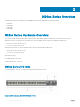
2 N20xx Series Overview The Dell N20xx switches are stackable Layer 2 Gigabit Ethernet switches and include the following models: • Dell N2024 • Dell N2024P • Dell N2048 • Dell N2048P N20xx Series Hardware Overview This section contains information about device characteristics and modular hardware configurations for the N20xx Series switches. All N20xx non-power over Ethernet (PoE) models are 1U, rack-mountable switches with the following physical dimensions: • 440.0 x 257.0 x 43.5 mm (W x D x H).
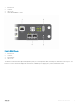
1 Console Port 2 USB Port 3 SFP+ Ports 4 48 10/100/1000BASE-T Ports Figure 2. N2024 Close-up 1 Console Port 2 USB Port 3 Reset Button 4 SFP+ Ports The N20xx I/O-side has status light emitting diodes (LEDs) for overtemperature alarm, internal power, and status on the top row. The bottom row of the status LEDs display the stack master, redundant power supply (RPS) status, and fan alarm status.
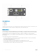
Figure 3. N2024P Close-up 1 Console Port 2 USB Port 3 Reset Button 4 SFP+ Ports The N20xxP I/O-side has status LEDs for the overtemperature alarm, internal power, and status on the top row. The bottom row of the status LEDs display the stack master, modular power supply units (MPS) status, and fan alarm status. Switch Ports The N2024/N2024P I/O-side provides 24 Gigabit Ethernet (10/100/1000BASE-T) RJ-45 ports that support autonegotiation for speed, flow control, and duplex.
Console Port The console port provides serial communication capabilities, which allows communication using the RS-232 protocol. The serial port provides a direct connection to the switch and allows access to the command line interface (CLI) from a console terminal connected to the port through the provided serial cable. The console port is separately configurable and can run as an asynchronous link from 1,200 baud to 115,200 baud. The Dell CLI only supports changing the speed.
N20xx Series PSU-Side The following image shows the PSU-side of the N20xx switches. Figure 4. N20xx PSU-Side 1 Mini-SAS stacking ports 2 Fan Vents 3 To DC Power Source (Optional) 4 AC Power Receptacle The term mini-SAS refers to the stacking port cable connections. For information about using the mini-SAS ports to connect switches, see the Stacking Multiple N20xx Switches section. Figure 5.
1 Mini-SAS stacking ports Power Supplies - N2024 and N2048 N2024 and N2048 switches have an internal 100-watt power supply. The additional redundant power supply (Dell Networking RPS720) provides 180 watts of power and gives full redundancy for the switch. Power Supplies - N2024P and N2048P Dell Networking N2024P and N2048P switches have an internal 1000-watt power supply feeding up to 24 PoE devices at full PoE+ power (850W).
3 N20xx Series Installation You can mount the N20xx Series switches in a standard 48.26 cm (19-inch) rack or placed on a flat surface. Make sure that the installation location meets the following site requirements: • Power — The switch is installed near an easily accessible 100–240 VAC, 50–60 Hz outlet. • Clearance — There is adequate front and rear clearance for operator access. Allow clearance for cabling, power connections, and ventilation.
Rack Mounting an N20xx Switch WARNING: Read the safety information in the Safety and Regulatory Information and the safety information for other switches that connect to or support the switch. The AC power connector is on the PSU-side of the switch. Installing in a Rack WARNING: Do not use rack mounting kits to suspend the switch from under a table or desk, or attach it to a wall. CAUTION: Disconnect all cables from the switch before continuing.
Figure 7. Mounting the N20xx in a 2-Post Rack Installing as a Free-standing Switch NOTE: Dell strongly recommends mounting the switch in a rack. Install the switch on a flat surface if you are not installing it in a rack. The surface must support the weight of the switch and the switch cables. The switch is includes four self-adhesive rubber pads. 1 Attach the self-adhesive rubber pads on each location marked on the bottom of the switch. 2 Set the switch on a flat surface.
Stacking Multiple Switches on Dell Networking OS 9.11(0.0) The system supports PE stacking, which allows multiple units to act as a single port extender. You can stack up to eight units using the stack ports on the PSU-side. The stack ports support the serial attached SCSI (SAS) protocol and operate as mini-SAS ports. The system supports stacking only with port extenders of the same series. The stack operates and is managed as a single entity.
1 Stack units 2 Stacking cables The ring topology stack has the following physical connections between the switches: • The bottom mini-SAS port on Unit 1 is connected to the top mini-SAS port on Unit 2. • The bottom mini-SAS port on Unit 2 is connected to the top mini-SAS port on Unit 3. • The bottom mini-SAS port on Unit 3 is connected to the top mini-SAS port on Unit 1. Stacking Standby on Dell Networking OS 6.3(0.16) The stacking feature on Dell Networking OS version 6.3(0.
4 Starting and Configuring the N20xx Switch Connecting an N20xx Switch to a Terminal After completing all external connections, connect a terminal to a switch to configure the switch. NOTE: Read the Release Notes for this product before proceeding. Dell Networking recommends that you obtain the most recent version of the user documentation from the Dell Support website at http://www.dell.com/support.
Figure 9. N2024P Console Port Location 1 Console port Connecting an N20xx Switch to a Power Source WARNING: Read the safety information in the Safety and Regulatory Information manual and the safety information for other switches that connect to or support the switch. All N20xx models have one internal power supply. The power receptacles are on the PSU-side.
Figure 10. AC and DC Power Connection to an N2024P/N2048P Switch 1 To DC Power Source (Optional) 2 To AC Power Source Booting the N20xx Switch When you turn on the power with the local terminal already connected, the switch goes through a power-on self-test (POST). POST runs every time the switch initializes and checks the hardware components to determine if the switch is fully operational before booting. If POST detects a critical problem, the program flow stops.
• The IP subnet mask for the network. • The IP address of the management interface default gateway. These settings are necessary to allow the remote management of the switch through Telnet (Telnet client) or HTTP (Web browser). Enable Remote Management On the N20xx switches, you can use any of the switch ports on the I/O-side for in-band management. By default, all in-band ports are members of virtual local area network 1 (VLAN 1)..
• • An IP address is configured for the VLAN 1 routing interface. A default gateway address is configured. In the following example, the possible user options or default values are enclosed in [ ]. If you press Enter without defining options, the default value is accepted. Help text is in parentheses. Performing Initial Configuration on Dell Networking OS 9.11(0.0) Before proceeding, ensure that the C9010 switch runs Dell Networking OS version 9.11(0.0) or later.
PORT-EXTENDER CONFIGURATION mode Dell(conf-pe-0)# cascade interface interface-type slot/port-range 5 • interface interface-type specifies a C9010 10-Gigabit Ethernet interface. The only supported value is TenGigabitEthernet slot/port-range. • slot/port-range specifies a C9010 10 GbE port, including slot number and either a single port number, a port range, or a combination of both for auto-LAG configuration. • The range of slot numbers is from 0 to 11.
NOTE: In the User-Configured Cascade Ports field, A (active) indicates that a C9010 port is up (no shutdown) and configured as a cascade port; I (inactive) indicates that a port is down and configured as a cascade port.
5 N30xx Series Overview The Dell N30xx switches are stackable Layer 2 (L2) and Layer 3 (L3) Gigabit Ethernet switches and include the following models: • Dell N3024 • Dell N3024P • Dell N3048 • Dell N3048P • Dell N3024F N30xx Series Hardware Overview This section contains information about device characteristics and modular hardware configurations for the N30xx Series switches. All N30xx models are 1U, rack-mountable switches with the following physical dimensions: • 434.0 x 407.0 x 43.
Figure 12. N3048 with 48 10/100/1000BASE-T Ports (I/O-Side) The I/O-side of each model in the N30xx series includes the following ports: 1 Console port 2 USB port 3 SFP+ Ports 4 Combo Ports 5 10/100/1000BASE-T Auto-sensing Full Duplex RJ-45 Ports The combo ports are SFP on the N30xx series and 1000BaseT on the N3024F switch. Figure 13.
6 Combo Ports The N30xx I/O-side above also contains a reset button (pinhole) and several status LEDs. The N30xx/N3024F/N30xxP I/O-side displays status LEDs for over-temperature alarm, internal power supply 1, and switch status on the top row. The bottom row of status LEDs displays stack master, internal power supply 2, and fan alarm. Switch Ports The N3024/N3024P I/O-side provides 24 Gigabit Ethernet (10/100/1000BASE-T) RJ-45 ports that support auto-negotiation for speed, flow control, and duplex.
The USB port does not support any other type of USB device. Reset Button The reset button is accessed through the pinhole and allows you to perform a hard reset on the switch. To use the reset button, insert an unbent paper clip or similar tool into the pinhole. When the switch completes the boot process after the reset, it resumes operation with the most recently saved configuration. Any changes made to the running configuration that were not saved to the startup configuration prior to the reset are lost.
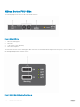
Figure 15. N30xx PSU-Side 1 AC Power Receptacle 2 Dual 10G Slots for SFP+, 10GBASE-T, or Stacking/10GbE Modules 3 Mini-SAS stacking ports 4 Fan Vents Figure 16. N3048 Mini-SAS Stacking Ports Close-up 1 Mini-SAS stacking ports The term mini-SAS refers to the stacking port cable connections. For information about using the mini-SAS ports to connect switches, see the Stacking Multiple N30xx Switches section.
Expansion Slots for Plug-in Modules One expansion slot is located on the back of the N30xx models and supports the following modules: • 10GBASE-T module • SFP+ module Each plug-in module has two ports. The plug-in modules include hot-swap support, so rebooting the switch after you install a new module is not necessary.
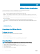
Marketing Model Name Description Power Supply Unit Regulatory Model Number Regulatory Type Number Units (PSUs)/1x Removable Fan Module N3024F 24x1G SFP/2x1G combo/ 200W 2x10G SFP+/2x Stacking/ 1x Modular Bay/N+1 Redundant Pluggable PSUs/1x Removable Fan Module E07W E07W003 N3024P 24x1G/2x1G combo/ 1100W/715W 2x10G SFP+/2x Stacking/ 1x Modular Bay/N+1 Redundant Pluggable PSUs/24x PoE + ports/12 UPoE Capable Ports/1x Removable Fan Module E06W E06W001 N3048 48x1G/2x1G combo/ 2x10G SFP+/2x Stackin
6 N30xx Series Installation You can mount the N30xx Series switches in a standard 48.26 cm (19-inch) rack or placed on a flat surface. Make sure that the chosen installation location meets the following site requirements: • Power — The switch is installed near an easily accessible 100–240 VAC, 50–60 Hz outlet. • Clearance — There is adequate front and rear clearance for operator access. Allow clearance for cabling, power connections, and ventilation.
5 Inspect the product and accessories for damage. Rack Mounting an N30xx Switch You may either place the switch on the rack shelf or mount the switch directly into a 19" wide, EIA-310-E compliant rack (four-post, twopost, or threaded methods). The Dell ReadyRail system is provided for 1U front-rack, and twopost installations. The ReadyRail system includes two separately packaged rail assemblies. WARNING: This is a condensed reference.
Figure 17. 1U Tool-less Configuration 2-Post Flush-Mount Configuration To install the Dell ReadyRails system using the two-post flush-mount configuration, follow these steps. 1 For this configuration, remove the castings from the front side of each ReadyRails assembly. See item 1 in Figure 18. Use a Torx driver to remove the two screws from each front flange ear (on the switch side of the rail) and remove each casting. Retain the castings for future rack requirements.
2-Post Center-Mount Configuration To install the Dell ReadyRails system using the two-post center-mount configuration, follow these steps. 1 Slide the plunger bracket rearward until it clicks into place and secure the bracket to the front post flange with two user-supplied screws. See item 1 in Figure 19. 2 Slide the back bracket towards the post and secure it to the post flange with two user-supplied screws. See items 2 and 3. 3 Repeat this procedure for the second rail. Figure 19.
Figure 20. 4-Post Threaded Configuration Install the N30xx System You can mount the system in the 1U front-rack or 1U two-post (flush and center) configurations. The following is an example of a frontrack configuration. For the 1U two-post (flush and center) configurations, slide the system into the rails in the same manner as the four-post configurations. Installing a 1U Front-Rack You must configure the rails that are attached to the system.
Figure 21. Attaching the Switch Rails 2 1 Front standoff locking tab 3 Locking tab 2 Switch After you have installed both switch rails, line them up on the previously mounted ReadyRails and slide the switch in until it is flush with front of rack. About 3 inches before you fully insert your system, the rail locking feature engages to keep the switch from inadvertently sliding out of the rack and falling. NOTE: Do not the use the mounted ReadyRails as a shelf or a workplace.
Figure 22. Installing the N30xx in a Front-Rack Configuration 1 Switch 3 Mounting screw 2 Rail bracket Installing as a Free-standing Switch NOTE: Dell Networking strongly recommends mounting the switch in a rack. Install the switch on a flat surface if you are not installing it in a rack. The surface must be able to support the weight of the switch and the switch cables. The switch is supplied with four self-adhesive rubber pads.
Stacking Multiple N30xx Switches on Dell Networking OS 6.3(0.16) If you are using Dell Networking OS 6.3(0.16), you can stack up to 12 switches using the mini-SAS ports located on the rear of the switch. N30xx switches only support stacking with other N30xx switches. When you connect multiple switches together through the stack ports, they operate as a single unit with up to 576 I/O-side ports. The stack operates and is managed as a single entity.
Figure 23. N30xx Stack in a Ring Topology 1 N30xx stack 2 Mini-SAS cables attached in a ring topology The ring topology stack has the following physical connections between the switches: • The bottom mini-SAS port on Unit 1 is connected to the top mini-SAS port on Unit 2. • The bottom mini-SAS port on Unit 2 is connected to the top mini-SAS port on Unit 3. • The bottom mini-SAS port on Unit 3 is connected to the top mini-SAS port on Unit 1. Stacking Standby on Dell Networking OS 6.3(0.
Although the Standby unit is automatically selected in the stack, you can use the CLI on the C9010 or the N20xx/N30xx series system console to manually configure a different stack member as Standby.
7 Starting and Configuring the N30xx System This section explains how to start and configure the N30xx system. Topics: • Connecting an N30xx Switch to a Terminal • Connecting N30xx Switch to Power Source • Booting the N30xx Switch • Initial Configuration Connecting an N30xx Switch to a Terminal After completing all external connections, connect a terminal to a switch to configure the switch. NOTE: Read the Release Notes for this product before proceeding.
Figure 24. N3048 Console Port Location 1 Console port The RJ-45 port to the right of the console port is the out-of-band management interface. Connecting N30xx Switch to Power Source WARNING: Read the safety information in the Safety and Regulatory Information manual and the safety information for other switches that connect to or support the switch. The N30xx switches have two FRU power supplies for redundant or load sharing operation.
Figure 25. Two Redundant Power Supplies on N3048 Switch 1 To AC Power Source Booting the N30xx Switch When you turn on the power with the local terminal already connected, the switch goes through a power-on self-test (POST). POST runs every time the switch initializes and checks hardware components to determine if the switch is fully operational before booting. If POST detects a critical problem, the program flow stops. If POST passes successfully, valid firmware loads into RAM.
• The IP subnet mask for the network. • The IP address of the management interface default gateway. These settings are necessary to allow the remote management of the switch through Telnet (Telnet client) or HTTP (Web browser). Enabling Remote Management The N30xx switch’s I/O-side contains a Gigabit Ethernet port for OOB management. The OOB port is located to the right of the console port.
The setup wizard configures the initial values. After completing the wizard, the switch is configured as follows: • • • • • • SNMPv2 is enabled and the community string is set up. SNMPv3 is disabled by default. The admin user account is set up as defined. A network management system is configured. From the management station, you can access the SNMP, HTTP, and CLI interfaces. You may also choose to allow all IP addresses to access these management interfaces by choosing the (0.0.0.0) IP address.
Please enter the SNMP community string to be used. [public]: public NOTE: If it is configured, the default access level is set to the highest available access for the SNMP management interface. Initially only SNMPv2 is activated. SNMPv3 is disabled until you return to configure security access for SNMPv3 (for example, engine ID, view, and so on.). Please enter the IP address of the Management System (A.B.C.D) or wildcard (0.0.0.0) to manage from any Management Station. [0.0.0.0]: 10.1.2.
This is the configuration information that has been collected: SNMP Interface = “public”@10.1.2.100 User Account setup = admin Password = ******** Out-of-band IP address = DHCP VLAN1 Router Interface IP = 10.1.1.200 255.255.255.0 Default Gateway = 10.1.1.1 Step 6: If the information is correct, please enter (Y) to save the configuration and copy the settings to the start-up configuration file.
The C9010 port-channel interface enabled for PE communication consists of member ports configured with the cascade port command. Provisioning a Port Extender You can provision an N30xx system with an initial software configuration before or after you install and power on the PE. To provision an N30xx system, start from the C9010 console and enter the following commands.
Example of Provisioning a Port Extender Dell(conf)# feature extended-bridge Dell(conf)# pe provision 2 Dell(conf-pe-2)# stack-unit 0 type n3048p Dell(conf-pe-2)# cascade interface tengigabitethernet 0/1–2 Dell(conf-pe-2)# exit Dell(conf)# interface range tengigabitethernet 0/1-2 Dell(conf-if-te-0/1–2)# no shutdown Dell(conf-if)# end Dell# show pe brief -- Port Extenders Information ----------------------------------------------------------PE-id Status Stack-size Type System-MAC -----------------------------